CSSE2010 — Week 9 Notes
Lecture 17 — Interrupts
The last of the four ways the program counter leaves its sequence. The list is branches, jumps, procedures, interrupts/traps, and the first three are in Lecture 15 (2026-09-14-flow-of-control). An interrupt is a call that nobody wrote: a device signals the CPU, and the hardware diverts the running program into a handler and later puts it back exactly where it was. The stack comes first, because that is where exactly where it was is kept. Then comes the problem the CPU has with slow I/O and the two ways to solve it, polling and interrupts, followed by the three issues an interrupt raises: finding the handler, preserving the registers, and what to do when a second interrupt arrives. Each issue gets the AVR’s answer, in assembly and in C. Traps, the software counterpart, come last. The evergreen notes are polling-and-interrupts (the mechanism, on any CPU) and avr-interrupts (the ATmega324A’s vector table, the ISR template, ISR() in C, and setting an interrupt up); the stack itself is procedures-and-the-stack.
The fast CPU and slow I/O
The topic is input/output: the stack revisited, then polling, then interrupts. The stack is what the rest is built on.
The problem is the interface between a fast CPU and slow I/O:
\[\text{CPU (FAST)} \;\longleftrightarrow\; \text{I/O (SLOW)}\]
On the ATmega324A block diagram (avr-architecture), the CPU side is the AVR CPU, running at 8 MHz, with FLASH and SRAM. The I/O side is PORT A, PORT B, PORT C, the A/D converter, and the three timer/counters 8bit T/C 0, 16bit T/C 1 and 8bit T/C 2.
Everything on the I/O side runs at the pace of the outside world. A pin changes when someone presses a button, a timer matches when its count gets there, a converter finishes when the conversion is done. Meanwhile the CPU is completing an instruction every one or two cycles of an 8 MHz clock. For scale, a button held down for a tenth of a second spans 800 000 of those cycles. The question is how the fast side finds out when the slow side has something for it.
AVR Stack
Two instructions move one register on and off the stack:
push Rrplaces the value in registerRron top of the stack, then adjusts the stack pointer: SP ← SP − 1.pop Rdplaces the value on top of the stack in registerRd, and adjusts the stack pointer: SP ← SP + 1.
The procedure-call instructions are call, rcall, icall and ret. For example, call label does three things:
- it places the program counter value (the return address) on top of the stack;
- SP ← SP − 2, since 16 bits are needed for the return address;
- PC ← the value of
label.
The stack is in data memory and grows towards address 0x000. Say the stack already holds some earlier values and Rr holds 100. push Rr writes 100 into the cell SP points at, the empty cell just above the earlier values, and leaves the stack pointer one cell further up, at SP − 1. pop Rd moves the stack pointer back down and takes the 100 out into Rd.
This is the summary of procedures-and-the-stack, and one detail matters for everything that follows: SP points at the next free cell, so a push writes first and then decrements, and a pop increments first and then reads. A call lowers SP by 2 because the stack is 8 bits wide and a return address is not, so a call uses two cells.
Function call — example
In program memory, main: has a few instructions and then call TEST. The instruction after the call is at address 100. Further down is TEST:, whose instructions end in ret. The call and the return take five steps:
- PC ← 100
- push PC, which puts the 100 on the stack
- PC ← TEST, and
TESTruns - pop PC, at the
ret - the instruction at address 100 runs
Step 1 is the return address: 100 is the address of the instruction after the call, which is where the PC would have gone next anyway. The call saves it, overwrites the PC with the target, and ret puts the saved value back.
Program memory has 2¹⁴ cells, so an address is 14 bits. The stack is in data memory, where a cell is 8 bits wide. The address does not fit in one cell, so the 100 takes the two cells above the earlier values and the stack pointer is left at SP − 2:
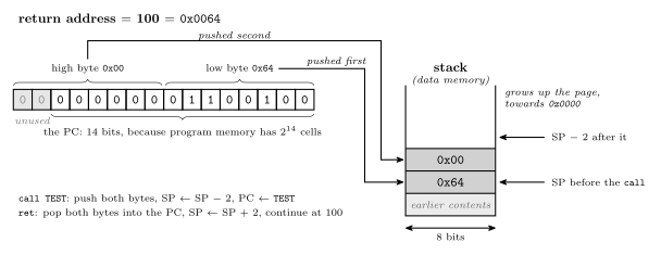
Figure 1: Why a call moves the stack pointer by two. Program memory on the ATmega324A has \(2^{14}\) cells, so the program counter is 14 bits wide, and the return address it holds (here 100, the address of the instruction after the call) does not fit in one byte. The stack is data memory, 8 bits to a cell, so the address is padded to 16 bits and stored as two bytes: the low byte goes into the free cell the stack pointer marks, the high byte into the one above it, and the stack pointer ends two cells further up, at SP − 2. ret reads the same two cells back into the PC and moves SP down by two. A push or pop of a register moves one byte and changes SP by one; mixing the two up is how a procedure that pushes without popping ends up returning to a register’s contents.
Worked: what is in r17 and r18?
What values are in r17 and r18 after this code?
ldi  r17, 20
ldi  r18, 33
push r17
push r18
pop  r17
clr  r17
pop r17| r17 | r18 | |
|---|---|---|
| A. | 0 | 20 |
| B. | 0 | 33 |
| C. | 20 | 20 |
| D. | 20 | 33 |
| E. | 33 | 20 |
| F. | 33 | 33 |
Answer: D. Take the instructions in the order they run and keep a running record of the two registers. r17 = 20 after its ldi, then 33 after the first pop, then 0 after the clr, then 20 after the second pop. r18 = 33 throughout. After the two pushes the stack holds 20 with 33 on top of it. The first pop takes the 33 back off and the second takes the 20.
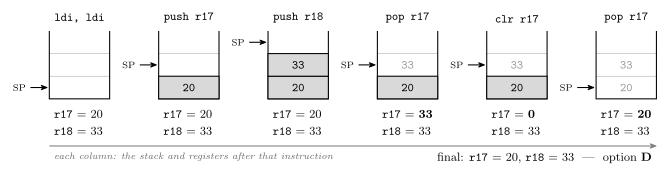
Figure 2: The seven instructions, with the stack drawn after each one (the two ldis share the first column). The stack pointer always marks the next free cell, and the stack grows up the page. The question turns on pop taking whatever is on top, with no record of which register put it there: the first pop r17 receives the 33 that r18 pushed, clr zeroes r17, and the second pop r17 receives the 20 that r17 pushed originally, so the clr has no lasting effect. r18 is never written after its ldi. A popped value is not erased; it stays in memory (grey) but sits above the stack pointer, so the next push will overwrite it.
The trap is reading pop r17 as give r17 back its value. The stack keeps values, not names: pushes and pops are matched by order, not by register, which is also what makes the stack useful for swapping two registers or handing a value from one to another. The two pushes and two pops balance, so the stack pointer ends where it began. That matters for interrupts, because an ISR that leaves the stack unbalanced returns to the wrong place.
CPU Interacting with I/O
The CPU operates at a faster speed than I/O, and I/O can sometimes be asynchronous. The CPU needs to know:
- when data is available from input devices;
- when output devices are ready to accept data.
There are two options: polling-driven I/O and interrupt-driven I/O.
Asynchronous is the harder half: I/O is not just slow, it is unrelated to the CPU’s clock and to where the program is, so a key can be pressed during any instruction. The two options are drawn side by side against the same events in polling-and-interrupts.
Polling the Input(s)
In polling, the processor periodically asks devices and waits for responses. This is inefficient, because time is wasted asking and waiting, but it may be OK if the processor has nothing else to do.
Polling is what every lab program so far has done: read PINA each time round the main loop, or spin on TIFR1 until the timer flag is set (avr-timers-and-counters). It costs in two places: every ask that finds nothing, and the delay between an event and the next ask. When the processor has nothing else to do, neither cost matters.
Interrupts
With interrupts, the device tells the CPU when it is ready. This is more efficient for the CPU, and it changes the flow of control. Examples:
- a device is ready to accept more output: the serial transmit buffer is empty;
- a device has input ready: a key is pressed on the keyboard;
- a regular interrupt: a timer generates an interrupt every e.g. 20 ms.
An interrupt arrives while some instruction of main is running. Each source of interrupt has its own routine, such as ISR0: and ISR_timer:, sitting in program memory below main like any procedure, and each ends in reti rather than ret.
The three examples are the three kinds of source that the AVR vector table below groups: output ready (a USART’s data register empty), input ready (an external interrupt pin), and time (a timer’s compare match or overflow). The change in the flow of control is the link back to Lecture 15. The PC leaves its sequence, as it does for a branch, jump or call, but here no instruction in the running program asks it to.
Interrupts — the handler, and three issues
When the CPU receives an interrupt, it executes software to handle the interrupt. The software routine is called an interrupt handler or interrupt service routine (ISR). When the handler completes, control must be returned to where the program left off. That raises three issues:
- How does the CPU know where the ISR is?
- All registers, including the status register, must have their values preserved. How?
- What happens if another interrupt arrives while an interrupt is being serviced?
Issue 1 is answered by the vector table, issue 2 by transparency and the ISR template, and issue 3 by nesting and priority.
Finding the Interrupt Handler
This is issue 1. The CPU determines the address of the ISR from the interrupt source, then jumps to that address. It finds the address by looking in the interrupt vector table, which is often at the beginning of memory. The table is either a table of addresses or a table of jump instructions. The AVR uses a table of jump instructions.
Vector sometimes refers to the interrupt number (the index into the vector table) and sometimes to the address of the interrupt handler itself.
The two kinds of table differ in who does the last step. With a table of addresses, the CPU reads the entry for the source and loads the number it finds into the PC. With a table of jumps, the CPU loads the PC with the address of the entry itself, and the instruction stored there — a jmp — does the rest. The AVR does the second. That is why each AVR entry is a two-word jmp (avr-branches-and-jumps) and why consecutive entries are two addresses apart.
The two meanings of vector are worth keeping in mind when reading the datasheet and avr-libc. The vector number is the entry’s row in the table (INT0 is vector 2), and the vector address is where that row sits in program memory (0x0002). In C, the vector’s name (INT0_vect) identifies the entry. avr-libc numbers the entries from 0, with RESET as 0, so the same entry is its vector 1: one more reason to check which counting is meant.
Finding the Interrupt Handler — the whole path
Take a timer interrupt that arrives while an instruction of main is running. Call the return address xxx. Below main in program memory are the handlers, ISR_timer: and ISR0:, each ending in reti. The vector table is at the very top of program memory:
| Entry | Address |
|---|---|
jmp ISR0 |
0x0000 |
jmp ISR1 |
0x0002 |
| ⋮ | |
jmp ISR_timer |
0x0014 |
The hardware pushes the return address xxx onto the stack (push PC) exactly as a call would, loads the PC with the table address for the source (0x0014), and the jmp stored there reaches ISR_timer. The handler’s reti then pops the return address back into the PC (pop PC), and main carries on. The numbering of the first two entries is generic: on the ATmega324A, 0x0000 is RESET and 0x0002 is INT0. The third is exact. 0x0014 is vector 11, Timer/Counter2 Compare Match B, so ISR_timer is the right name for what sits there. The path is drawn step by step, with the stack, in avr-interrupts.
AVR Interrupts
The vector table of the ATmega324A (datasheet, pages 69-70). The last column sorts the sources into kinds of I/O:
| Vector | Program Addr | Source | Interrupt Definition | Kind |
|---|---|---|---|---|
| 1 | 0x0000 | RESET | RESET, Watchdog Reset, etc. | |
| 2 | 0x0002 | INT0 | External Interrupt Request 0 | GPIO |
| 3 | 0x0004 | INT1 | External Interrupt Request 1 | GPIO |
| … | ||||
| 11 | 0x0014 | TIMER2_COMPB | Timer/Counter2 Compare Match B | T/C |
| 12 | 0x0016 | TIMER2_OVF | Timer/Counter2 Overflow | T/C |
| … | ||||
| 20 | 0x0026 | SPI_STC | SPI Serial Transfer Complete | Comms |
| 21 | 0x0028 | USART0_RX | USART0 Receive Complete | Comms |
| 22 | 0x002A | USART0_UDRE | USART0 Data Register Empty | Comms |
| 23 | 0x002C | USART0_TX | USART0 Transmit Complete | Comms |
| 24 | 0x002E | ANALOG_COMP | Analog Comparator | |
| … |
Three things can be read straight off it:
- Address = 2 × (vector − 1). Entries are two program-memory words apart because each holds a two-word
jmp. - RESET is vector 1. Reset is handled as the first entry of the same table, which is why every program begins with
jmp RESETat0x0000(avr-program-structure). - The three groups are kinds of I/O. GPIO: pins that raise an interrupt on an edge or level. T/C: the timers. Comms: the serial interfaces. The first two are the ports and timers on the I/O side of the block diagram.
All 31 rows, with their C names, are listed in avr-interrupts.
Preserving Register Values
This is issue 2. If an ISR uses registers, it must save copies of those registers before using them and restore the values afterwards, before returning from the interrupt. In particular, the status register must be saved. Many CPUs do this automatically. The AVR does not: it must be done manually, if the status register would be changed by the handler. This is called transparency: when the ISR finishes, the computer is in the same state as it was before the interrupt.
A procedure’s caller knows the call is coming and can agree with the procedure which registers it may use (procedures-and-the-stack). The code an interrupt lands in has no such chance: the interrupt can arrive between any two instructions. That includes the gap between a cp and the breq that reads its result. If the ISR changes Z and does not put it back, the branch goes the wrong way. It does so only when the interrupt happens to land in that two-instruction window, which is what makes the bug so hard to find. So everything the ISR touches must be restored, the status register above all, and the ISR is then transparent: the interrupted program cannot tell it ran.
Interrupt Summary — Sequence of Actions
The whole sequence is fourteen steps, shared between the hardware and the ISR. Hardware:
- Device asserts interrupt line
- CPU determines source of interrupt
- Push PC (return address) onto stack
- Some CPUs push the status register as well, but not the AVR
- Determine address of ISR (e.g. from the interrupt vector table)
- CPU puts address of ISR into PC
- CPU disables interrupts
Software (ISR):
- Save all registers to be used
- Determine source of interrupt (if this is not done by hardware)
- Handle the interrupt by executing the ISR code (e.g. do the required input or output)
- Restore registers
- Execute return from interrupt instruction
Back to hardware:
- Interrupts are re-enabled
- CPU pops PC off the stack and restores it
- Execution continues from where it was “interrupted”
Steps 6 and 12 are a pair. On the AVR, disables interrupts is the hardware clearing the I bit of the status register (avr-architecture) as it takes the vector, and re-enabled is reti setting it again. Between them, no other interrupt can start. Step 8 mostly does not arise on the AVR, because every source has its own vector and so the hardware has already told the ISR which source fired. The exception is the pin-change interrupts: PCINT0–PCINT3 each cover a whole port, and their handler must work out which pin changed. Steps 11 to 13 are a single instruction: reti is ret plus set I. The whole sequence is drawn, with the stack and the I bit at each stage, in polling-and-interrupts.
Instructions which change the Status Register
The Instruction Set Reference says which instructions change the status register. Its Flags affected column is summarised for the instructions this course uses in avr-instructions. The short version is enough to decide whether an ISR must save SREG:
| Change flags | Change no flags |
|---|---|
arithmetic: add, adc, sub, subi, inc, dec, neg |
data movement: ldi, mov, lds, sts |
logic: and, andi, or, ori, eor, com, clr, tst |
I/O: in, out, sbi, cbi |
compare: cp, cpi |
stack: push, pop |
shifts and rotates: lsl, lsr, asr, rol, ror |
jumps, calls, returns and branches |
An ISR built only from the right-hand column cannot disturb the flags, so it has no need to save them. The worked question after the ISR template tests that rule. (Three instructions change the I bit and nothing else: sei, cli and reti.)
Template AVR ISR
isr_label:                ; Save any registers used
            push r0
            in   r0, SREG
            push r0

            ; … perform operation
            ; … (usually Input/output)

            ; Restore registers
            pop  r0
            out  SREG, r0
            pop  r0
            ; return from interrupt
            reti
The first three instructions store on the stack: r0, then the SREG copy that in r0, SREG takes and the second push r0 saves. The three before the reti restore from the stack: out SREG, r0 puts the flags back and the last pop r0 puts r0 back.
Each line is there for a reason:
r0is pushed first becauseSREGcannot be pushed directly.pushtakes a general-purpose register, andSREGis an I/O register, so its value has to travel through one. That register’s own contents must be saved before it is used as the carrier.- The flags saved are the interrupted program’s. Apart from I, which the next point covers, nothing between the interrupt and
in r0, SREGchanges them, sincepushdoes not touch the flags. They are exactly what the interrupted code last left inSREG. - The restore is the mirror image, because the stack returns things in reverse order. The saved
SREGcopy comes off first, so it is popped intor0and written toSREG; thenr0’s own value comes off. - The saved I bit is 0. The hardware cleared I before the first instruction of the ISR ran, so the copy taken by
in r0, SREGhas I = 0, and writing it back leaves interrupts off. It isreti, the last instruction, that turns them on again.
Any other register the body uses gets its own push after these three and its pop before the restore, in reverse order. The stack through the whole template is drawn in avr-interrupts.
Worked: a suitable ISR for port B to port C
Which of these is a suitable interrupt service routine that reads a byte from the port B pins and outputs it to port C? There are four handlers for INT0, each with .def temp = r16:
; (a)
int0: push temp
      in   temp, SREG
      push temp
      in   temp, PINB
      out  PORTC, temp
      reti
; (b)
int0: push temp
in temp, SREG
push temp
in temp, PINB
out PORTC, temp
pop temp
pop temp
out SREG, temp
reti; (c)
int0: push temp
in temp, SREG
push temp
in temp, PORTB
out PINC, temp
pop temp
out SREG, temp
pop temp
reti; (d)
int0: push temp
in temp, PINB
out PORTC, temp
pop temp
reti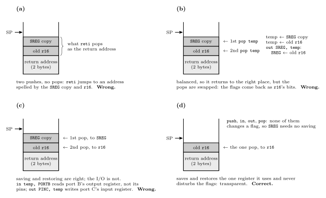
Figure 3: The four candidate handlers, each with its stack drawn at its fullest, just before it starts to unwind. (a) pushes two bytes and pops none, so reti takes the saved SREG copy and r16 as its return address and jumps into the program at an address made of them. (b) pops the two bytes in the wrong order: the stack is balanced, so it returns correctly, but SREG receives r16’s old value and the interrupted code resumes with meaningless flags. (c) saves and restores exactly as the template does, but reads PORTB, port B’s output register, instead of PINB, its pins, and writes to PINC, port C’s input register, instead of PORTC; on this chip a 1 written to a PINx bit toggles the matching PORTx bit, so the outputs would flip rather than copy port B. (d) saves the one register it uses and never touches the flags, since in, out, push and pop change none of them; it is correct, and the shortest.
The answer is (d). It looks the least careful of the four because it skips the SREG lines, but SREG has to be saved only if the status register would be changed by the handler, and nothing in (d) changes it. The other three each make a different mistake worth recognising. (a) leaves the stack unbalanced, (b) restores in the wrong order, and (c) confuses a port’s three registers (avr-io-ports). PINx is what the pins read, PORTx is what the port drives, and the two are not interchangeable. All four assume, as the question does, that port B’s pins were set as inputs and port C’s as outputs during initialisation.
AVR Interrupts in C
Start with #include <avr/interrupt.h>. An interrupt handler can then be written as a C function, using the special ISR macro:
ISR(INT0_vect) {
    … /* code here */
}
This is the handler for the INT0 external interrupt. The interrupt vector table setup and the register saving and restoring happen automatically. The name to use is the source name from the datasheet followed by _vect. The AVR LibC manual documents avr/interrupt.h.
The argument, INT0_vect, is the name that matters. ISR is not a function name but a macro, and what it is given is the vector. From that the compiler does the three things the assembly programmer does by hand: it places a jump to this function in the vector table at INT0’s entry (0x0002), wraps the body in the save-and-restore the template writes out, SREG included, and ends it with reti instead of ret. The naming rule is the Source column of the table plus _vect, which gives TIMER2_COMPB_vect, USART0_RX_vect, ANALOG_COMP_vect, and so on.
Setting up interrupts
Besides the handler, the program also needs to:
- set up the conditions for the interrupt;
- enable that particular interrupt. An I/O register bit for each interrupt controls whether that interrupt is enabled or not;
- clear the specific interrupt flag, to ensure the interrupt doesn’t trigger immediately. This is usually done by writing 1 to some I/O register bit;
- turn on interrupts globally, with the
sei()macro (the same as theseiassembly language instruction).
These are four switches, and an interrupt reaches its handler only when all of them are on. For a timer 1 compare-match interrupt:
| Step | Timer 1, compare A |
|---|---|
| conditions | TCCR1A/TCCR1B and OCR1A: the mode, prescaler and match value (avr-timers-and-counters) |
| enable that interrupt | OCIE1A in TIMSK1 |
| clear its flag | TIFR1 = (1<<OCF1A);, a 1 written to clear it |
| enable globally | sei();, which sets I in SREG |
Clearing the flag first matters because the flag is set by the hardware whether or not its interrupt is enabled. A timer that has been counting while the interrupt was off has very likely matched already. Without the clear, the moment the enable and sei() go on, the CPU would take a stale interrupt for an event that happened long before. The complete program is in avr-interrupts.
Volatile variables in C
A variable that can be changed outside the normal flow of a program (e.g. in an interrupt handler) should be declared as volatile:
volatile uint8_t count;This prevents the code optimiser from assuming the variable’s value doesn’t change and optimising code away.
For example, take a loop in main:
int i = 0;
while (i < 10) {
    …
}
and a handler that writes the variable:
ISR() {
    i = 100;
}
The optimiser concludes that the condition i < 10 is always TRUE.
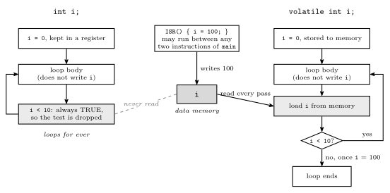
Figure 4: What volatile changes. main loops while i < 10, nothing in the loop body writes i, and an ISR sets i = 100. The compiler analyses main on its own and has no way to know that a handler may run between any two of its instructions. Without volatile it may keep i in a register, or conclude that i < 10 can never become false and drop the test entirely: the ISR’s write reaches memory, but the loop never reads memory again and never ends. With volatile, every read of i in the source becomes a load from memory in the machine code, so the first test after the ISR has run sees 100 and the loop exits. The program is identical in both columns; only what the compiler is permitted to assume differs.
The compiler is not wrong to optimise; it is working from a program that, as far as it can see, never changes i in the loop. volatile is how the programmer tells it about the other writer. The declaration of count uses uint8_t where the loop uses int, and uint8_t is the safer choice on this CPU, for a reason drawn out in avr-interrupts. A one-byte variable is read by a single instruction, so an interrupt cannot land halfway through reading it.
Nested Interrupts
This is issue 3. There is a chance that another device interrupts during ISR execution. There are two policies:
- Simply disable subsequent interrupts during the ISR. Usually, the global interrupt enable flag is one of the flags restored by the return from interrupt instruction.
- Better, prioritise interrupts, and allow higher priority interrupts to interrupt lower priority ones (and not vice versa, or at the same level). Many CPUs support this, but not the AVR.
The first is the AVR’s: interrupts are off for the whole ISR. On a CPU that saves the status register automatically, restoring it on return brings the enable flag back with everything else. The AVR does not save SREG, but reti sets I directly, which comes to the same thing. The second policy — priority nesting, where only a more urgent source may interrupt an ISR — is the better one, and the AVR does not have it. The three policies, including the one the AVR allows by choice, are compared in polling-and-interrupts.
AVR Interrupt Priority
Priority is determined by vector: the lowest vector is the highest priority. The top of the vector table is HIGH priority and the bottom is LOW. So RESET outranks everything, INT0 is the highest-priority real interrupt, and down the table external pins come before timers, which come before the serial interfaces.
Three rules say when priority applies:
- Priorities only matter when two (or more) interrupts are waiting to be serviced. The highest priority (lowest vector) is serviced first.
- Interrupts are disabled during an ISR, and re-enabled by the
retiinstruction. - It is possible to enable interrupts during an ISR. Priorities are not relevant then: any incoming (or pending) interrupt may be serviced, even if it is lower priority.
The first rule is the one people get wrong. On the AVR, priority does not mean that a more important interrupt can cut into a less important ISR. It only decides the order in which waiting interrupts are taken, once the CPU is free to take one. An interrupt waits by leaving its flag set, so nothing is lost while I is 0, as long as each source fires only once in the meantime.
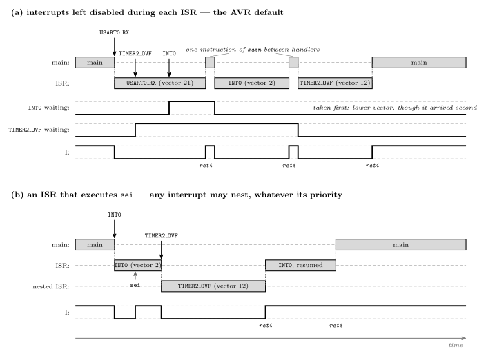
Figure 5: Two cases, each with the I bit traced underneath. (a) The default. While the USART0_RX handler runs, I is 0, so the timer overflow and then INT0 arrive and wait, their flags set (the two middle traces). When reti sets I again, the lower vector goes first: INT0 (vector 2) is serviced before TIMER2_OVF (vector 12) even though it arrived later. That ordering is the only thing priority does on the AVR. Between two handlers the CPU executes one instruction of main, as the datasheet specifies, so a steady stream of interrupts cannot starve the main program completely. (b) An ISR that executes sei early. From that instruction on, I is 1 and any interrupt is taken at once, however low its priority: the timer overflow nests inside the INT0 handler, and INT0’s handler finishes only after the nested one returns. The hardware saves nothing extra for the nesting; each level’s return address is simply one more pair of bytes on the stack.
The (b) case is sometimes exactly what is wanted. A long, unhurried handler can re-enable interrupts so that a time-critical source is not kept waiting. But it gives up the protection the default provides: the handler can now be interrupted by anything, including a second copy of itself if its own source fires again, and every level of nesting costs more stack. Nothing in the course’s labs needs it.
Traps
Traps are software interrupts: they are caused by events in software rather than hardware. The events are exceptional ones. Examples:
- overflow
- divide by zero
- undefined opcode
Traps save continually checking for errors. Trap handlers (service routines) don’t always return to the original program. The AVR doesn’t provide traps, but it is possible to generate hardware interrupts from software.
Traps are to error checking what interrupts are to polling. Without them, a program that cares about overflow has to test V after every addition, which is polling for errors. With them, the hardware watches, and the program is diverted only when the error actually happens. That a handler doesn’t always return follows from what the errors are: after a division by zero or an undefined opcode there is often no sensible instruction to continue with, and under an operating system the usual outcome is that the program is ended. On the AVR none of this exists. Overflow simply sets V for the program to test with a branch (avr-branches-and-jumps), and there is no divide instruction to fail. The hardware interrupts that software can generate are the external interrupt pins: the datasheet notes that INT0–INT2 still trigger when their pins are configured as outputs, so writing the pin’s PORT bit raises the interrupt on purpose.
See also
- polling-and-interrupts — polling versus interrupts, the fourteen-step sequence drawn, transparency, the three nesting policies, traps
- avr-interrupts — the ATmega324A vector table in full, the ISR template’s stack,
ISR()and the_vectnames, setting up an interrupt,volatile, a complete timer-interrupt program - procedures-and-the-stack —
push,pop,call,retand the stack pointer - avr-timers-and-counters —
TIMSKnandTIFRn, the timer interrupt registers - avr-program-structure — the
jmp RESETat the top of every program, and the vector table after it - avr-architecture — the status register and its I bit · avr-instructions — which instructions change the flags
- c-preprocessor-and-avr-headers —
volatileon the I/O register macros - 2026-09-14-flow-of-control — Lecture 15 · 2026-09-17-pulse-width-modulation — Lecture 16 · 2026-09-24-serial-io — Lecture 18 · 2026-10-05-more-io — Lecture 19,
volatileagain - week9-lab-avr-interrupts — Lab 14: interrupts in C on the board
Lecture 18 — Serial Input/Output
How a microcontroller talks to another computer over a single wire, and a first look at reading analog voltages. It covers serial against parallel and synchronous against asynchronous links, the UART frame with its start, data, parity and stop bits, how a receiver finds the bits with no shared clock, baud rate, and the ATmega324A’s USART: its registers and its three interrupts. The last part is the PC end of the link, RS232, and analog to digital conversion. The reference notes are serial-communication, avr-usart and analog-to-digital-conversion.
Where serial I/O fits
The parts of the ATmega324A used so far (avr-architecture):
| Part | What it has been used for |
|---|---|
| Ports A, B, C, D | switches, buttons and the seven-segment display (avr-io-ports, seven-segment-display) |
| CPU, flash, SRAM | running the program |
| Timer/counters 0, 1, 2 | timing, waveforms and PWM (avr-timers-and-counters) |
Three more blocks come into play from here:
- USART0 and USART1: two serial ports. A key typed in a terminal program on a PC travels down a wire and arrives in the microcontroller as a character, and the microcontroller can send characters back.
- SPI: the chip’s other serial interface, a synchronous one. It is the one that will drive the LED display.
- The A/D converter: reads a voltage, such as the position of a joystick, as a number.
The block diagram in the datasheet is shared by a family of chips and shows timers the 324A does not have. The 324A has exactly three: two 8-bit and one 16-bit.
Interrupt set-up, once more
A device can interrupt the CPU only when three things are true at once (avr-interrupts):
- Interrupts are enabled globally:
sei()has set the I bit, bit 7 ofSREG. - The device’s own interrupt is enabled: for a timer 1 compare match,
OCIE1AinTIMSK1. - The device’s interrupt flag is set:
OCF1AinTIFR1, set by the hardware when the event happens.
The set-up code makes the first two true and leaves them that way. The third is different, because the flag is set by the hardware, at the moment of the event. Set-up does two things about it. It configures the device so that the event will happen: for the timer that is the mode, the prescaler and a compare value such as OCR1A = 200, after which the flag is set every time the count reaches 200. And it clears the flag first, so that an event from before the program was ready does not fire the handler straight away. Clearing it is the step that reads backwards.
An interrupt flag is cleared by writing a 1 to it. Writing a 0 does nothing.
Check. Which of these is false when configuring interrupt-driven I/O?
- A. Global interrupts should be enabled
- B.
SREGbit 7 should be set to 1 - C. The interrupt should be enabled in the I/O device
- D. A 1 should be written to the particular interrupt flag bit
- E. A 0 should be written to the particular interrupt flag bit
E. A and B are the same statement, since bit 7 of SREG is the global enable. C is the device’s enable bit. D is how a flag is cleared.
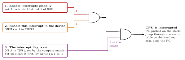
Figure 6: What has to be true for a timer compare match to interrupt the CPU, as the inputs of two AND gates. The set-up code puts the first two lines at 1 and they stay there. The third line is the flag, which the timer sets at each compare match, so the output goes to 1 only when the event happens. Without the first or the second the handler never runs. Set-up also clears the flag to begin with, by writing a 1 to it, so that an old event cannot run the handler straight away.
When the interrupt is taken, the address of the next instruction is pushed on the stack, the CPU jumps through the vector table to the handler, and reti pops the address to resume (procedures-and-the-stack).
Serial and parallel, synchronous and asynchronous
Two independent choices describe a communication link.
Serial or parallel is about how many wires carry data. A parallel link has one wire per bit and sends the bits together. A serial link has one wire, and the bits take turns. Serial needs fewer pins and wires, which is why almost every link between devices is serial.
Synchronous or asynchronous is about how the receiver knows when to look at the wire. A synchronous link sends a clock on a second wire alongside the data. An asynchronous link has no clock wire, so the receiver must recover the timing from the data itself, and the data must be encoded to make that possible.
| Example | |
|---|---|
| synchronous serial | SPI, Serial Peripheral Interface |
| asynchronous serial | UART, Universal Asynchronous Receiver and Transmitter; USB |
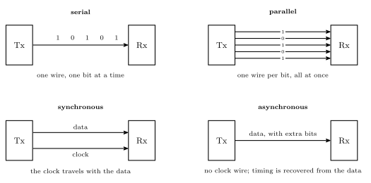
Figure 7: Four ways to join a transmitter to a receiver. Top row: the same five bits sent serially, one after another down a single wire, and in parallel, on five wires at once. Bottom row: two kinds of serial link. A synchronous link has a second wire carrying the clock that says when each data bit is valid. An asynchronous link has the data wire only, and the transmitter adds extra bits to the stream so that the receiver can work out the timing for itself.
The difficulty with no clock wire is that a run of identical bits is a flat line with nothing to time against. The encodings in use are different ways of guaranteeing edges:
- Start and stop bits: every character begins with a guaranteed edge. This is what a UART does.
- 4B/5B and 8B/10B: every 4 or 8 bits are sent as a 5- or 10-bit code chosen so that the line changes often.
- Bit stuffing: an opposite bit is inserted after a run of identical ones. USB at low and full speed does this.
The UART frame
The AVR’s serial port is a USART, a Universal Synchronous and Asynchronous Receiver/Transmitter. It can do both, and the course uses it mainly in asynchronous mode, so it is usually just called a UART. Three things characterise it:
- It is serial: data goes one bit at a time, in groups called frames.
- It is asynchronous: no clock is sent. Each end has its own clock. The two clocks can be quite different, as long as each end can derive nearly the same bit time from its own.
- It uses start and stop bits to mark each frame.
A frame is one character’s worth of data wrapped in framing bits, in this order:
| Field | Bits | Value |
|---|---|---|
| start bit | 1 | always 0 |
| data bits | 5 to 9 | the data, bit 0 first |
| parity bit | 0 or 1 | computed from the data; optional |
| stop bits | 1 or 2 | always 1 |
Between frames the line idles at 1. So a start bit is always a fall from 1 to 0, which is the event the receiver waits for, and the stop bit puts the line back at 1 so that the next start bit is a fall too. After the stop bit, either the next frame starts at once or the line stays idle.
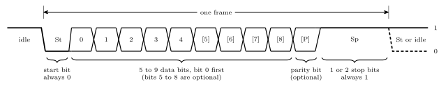
Figure 8: One UART frame, field by field. The line idles at 1. The start bit is always 0, so every frame begins with a falling edge. The data bits follow, least significant first: there are at least five and at most nine. The parity bit is optional. One or two stop bits, always 1, end the frame and return the line to its idle level, ready for the falling edge of the next start bit.
Parity
The parity bit is for error detection. Both ends agree on even or odd parity beforehand.
- Even parity: the number of 1s in the data bits plus the parity bit must be even.
- Odd parity: that number must be odd.
The transmitter works out the parity bit and sends it. The receiver counts the 1s in everything it received, parity bit included, and a count of the wrong kind means at least one bit was changed on the way.
Example. Nine data bits 0 0 1 0 0 1 1 1 1 contain five 1s. For even parity the parity bit is 1, making six. For odd parity it is 0, leaving five.
Check. 0xA7 is to be sent as 8 data bits with odd parity. What is the parity bit? 0xA7 is 1010 0111: two 1s and three 1s, five in all. Five is already odd, so the parity bit is 0.
Check. 0xA9 arrives with parity bit 1 on a link using even parity. Was there an error? 0xA9 is 1010 1001, four 1s. With the parity bit that is five, which is odd. Yes: at least one of the nine bits is not what was sent.
Parity can say that something went wrong. It cannot say which bit, and if two bits flip the count comes out right again and the error goes unnoticed. Finding and repairing the wrong bit is error correction, which takes more check bits arranged as a Hamming code and is not part of a UART frame.
How the receiver finds the bits
The receiver has to know the baud rate in advance, but its clock does not have to be synchronised with the transmitter’s. It works like this:
- It samples the line much faster than the bits arrive: 16 samples per bit on the AVR (8 in double-speed mode).
- The fall of the start bit starts it counting samples.
- It reads each bit from the three samples in the middle of that bit’s time, by majority vote. Three 0s in the middle of the first bit time confirm a real start bit and not a spike of noise.
Reading in the middle is what makes an unsynchronised clock tolerable. If the receiver’s bit time is a little long or short, its sampling point drifts a little further with every bit, and starting from the centre leaves half a bit of margin either way. The drift has only one frame to build up before the next start bit resets it.
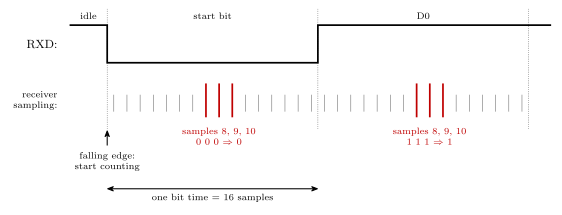
Figure 9: How a UART receiver reads a bit without a shared clock. It samples the line 16 times per bit. The falling edge of the start bit starts the count, and each bit is decided by a majority vote of the three samples at its centre, shown tall. Three 0s in the middle of the first bit time confirm a start bit. The same three positions in the next bit time read 1, 1, 1, so the first data bit is 1. Because the count restarts at every start bit, the two ends only have to agree on the bit time closely enough for the sampling point to stay inside the bit for one frame.
Baud rate
Baud rate = symbols per second. It is not the same as the bit rate, the number of useful data bits per second.
Every bit time on the wire is one symbol, whether it carries data or framing. With 8 data bits, no parity, one start bit and one stop bit, a frame is 10 symbols and carries 8 bits:
\[9600 \text{ baud} \times \tfrac{8}{10} = 7680 \text{ bits per second} = 960 \text{ bytes per second}\]
The industry-standard rates are 2400, 4800, 9600, 14400, 19200, 28800, 38400, 57600 and 115200.
On the AVR the rate is set by a number in the baud-rate register, worked out from the clock frequency and the 16 samples per symbol:
\[UBRRn = \frac{f_{OSC}}{16 \cdot BAUD} - 1\]
For 9600 baud with the 8 MHz clock: \(8\,000\,000 / (16 \times 9600) - 1 = 51.08\), so the register is 51. The real rate is then \(8\,000\,000 / (16 \times 52) = 9615\) baud, about 0.2 % fast, which is easily close enough. The datasheet tabulates the values for the standard rates (pages 198 to 201), and avr-usart works them out. The formula has the same shape as the timer’s master formula (avr-timers-and-counters) for the same reason: counting through the values 0 to \(N\) takes \(N + 1\) clock cycles, here with \(N = UBRR\).
The AVR USART
USART0 uses two pins of port D: PD0 is RXD0, receive, and PD1 is TXD0, transmit. The USART is described on pages 175 to 201 of the datasheet.
At the centre of each half is a shift register (shift-registers). To transmit, a byte written to the data register is loaded into the transmit shift register and shifted out of TxD one bit per bit time, with the framing bits added. To receive, bits arriving on RxD are shifted in one at a time, and the completed byte is copied to the data register. A UART is a parallel-to-serial converter and a serial-to-parallel converter with framing.
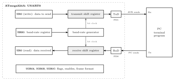
Figure 10: The USART reduced to what a program uses, joined to a PC. The baud-rate register sets the bit time for both halves. A byte written to the data register is copied into the transmit shift register and shifted out of the TxD pin, with the start, parity and stop bits added on the way. Bits arriving on RxD are shifted into the receive shift register, checked and stripped of their framing, and the byte is copied to the data register to be read. The two ends are cross-connected: each one’s transmit pin goes to the other’s receive pin.
A program works the USART through five I/O registers.
UDR0, the data register. One name, two registers: writing UDR0 puts a byte in the transmit buffer, and reading UDR0 takes a byte from the receive buffer. Reading it does not give back what was last written.
UCSR0A, UCSR0B, UCSR0C, the control and status registers.
| 7 | 6 | 5 | 4 | 3 | 2 | 1 | 0 | |
|---|---|---|---|---|---|---|---|---|
UCSR0A |
RXC0 |
TXC0 |
UDRE0 |
FE0 |
DOR0 |
UPE0 |
U2X0 |
MPCM0 |
UCSR0B |
RXCIE0 |
TXCIE0 |
UDRIE0 |
RXEN0 |
TXEN0 |
UCSZ02 |
RXB80 |
TXB80 |
UCSR0C |
UMSEL01 |
UMSEL00 |
UPM01 |
UPM00 |
USBS0 |
UCSZ01 |
UCSZ00 |
UCPOL0 |
The pattern that makes these readable:
- The top three bits of A are the interrupt flags: receive complete, transmit complete, data register empty.
- The top three bits of B, directly beneath them, are the matching interrupt enables. IE in each name is interrupt enable.
- C holds the frame format:
UPMselects the parity (none, even or odd) andUSBSselects one or two stop bits.
After reset, C is set for 8 data bits, no parity and one stop bit, the commonest format. Every bit is explained in avr-usart.
UBRR0, the baud-rate register. A 12-bit value held in two bytes, UBRR0H and UBRR0L. Either compute it from the formula or take it from the datasheet’s tables.
The three serial interrupts
Each serial port has three interrupt sources.
| Interrupt | Means |
|---|---|
| Receive complete | a frame, usually a character, has arrived and can be read |
| Transmit complete | a frame has been sent and no more data is waiting to go |
| Data register empty | the port is ready to accept another byte for transmission |
The last two are easy to confuse. The USART can hold two bytes on the way out: one in the shift register being sent, and one in the data register waiting. Data register empty means the waiting place is free, so the next byte can be written even though the previous one is still going out. Transmit complete means the last bit has left and nothing was waiting, so the line has gone idle.
The PC end
A PC has no UART pins. The IO board (io-board) has a USB-serial device on it, which appears to the PC as a serial port and presents the two serial lines to the breadboard. On the PC a terminal program such as PuTTY sends what is typed and shows what arrives. It has to be told:
- the COM port, which serial port to use (Device Manager shows which one the board has been given);
- the baud rate and the frame format: data bits, parity, stop bits.
Nothing on the wire announces these settings, so the two ends must simply be set the same. A mismatch gives wrong characters, not an error message.
RS232
RS232 is the long-established serial standard, more than forty years old and still in use, typically on a 9-pin D-sub connector. It carries the same frames at different voltages:
| AVR pin | RS232 | |
|---|---|---|
| logical 1 | 5 V | a negative voltage, −3 to −15 V |
| logical 0 | 0 V | a positive voltage, +3 to +15 V |
The levels are inverted as well as larger, so a converter chip such as the MAX-232 is needed between the two. RS232 is full duplex: it can transmit and receive at the same time, because each direction has its own wire. The minimum connection is three signals: transmit data (TxD), receive data (RxD) and ground.
Analog to digital conversion
Every input so far has been digital: the processor sees 0 or 1. An analog to digital converter (ADC) takes a voltage anywhere between 0 and a maximum, the reference voltage \(V_{ref}\), and turns it into a number in proportion.
An ADC has a resolution, the number of bits in its result. With 10 bits there are \(2^{10} = 1024\) possible results, 0 to 1023.
A joystick is the standard example. It produces two voltages, one for each direction of travel, and after conversion its position is a pair of numbers.
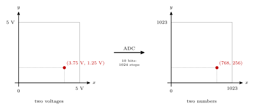
Figure 11: What a 10-bit converter does to a joystick. Left: the stick’s position as two voltages, each between 0 V and the reference, here 5 V. Right: the same position after conversion, as two numbers from 0 to 1023. The converter divides the range of each voltage into 1024 equal steps, about 4.9 mV each, and reports which step the voltage is on. The marked position, 3.75 V across and 1.25 V up, becomes 768 and 256.
On the ATmega324A:
- The port A pins can be used as analog inputs.
- One input is converted at a time. An analog multiplexer selects which pin is connected to the converter, so a joystick’s two voltages are read one after the other.
- \(V_{ref}\) can be chosen. The course uses \(V_{cc} = 5\ \text{V}\).
- The resolution is 10 bits, 0 to 1023.
- A conversion takes time: up to 3200 clock cycles, 0.4 ms at 8 MHz. Accuracy can be traded for speed.
0.4 ms is long enough for a couple of thousand instructions, so the end of a conversion is another event a program either polls for or takes as an interrupt (polling-and-interrupts). More in analog-to-digital-conversion.
See also
- serial-communication — serial and parallel, synchronous and asynchronous, the UART frame, parity, sampling, baud rate, RS232
- avr-usart — the USART’s registers bit by bit, the baud-rate values, code for sending and receiving, and the three interrupts
- analog-to-digital-conversion — resolution, the reference voltage, and the ATmega324A’s converter
- avr-interrupts · polling-and-interrupts — flags, enables and the global enable
- shift-registers — the conversion between parallel and serial at the centre of a UART
- avr-architecture — the block diagram · io-board — the USB-serial device
- avr-spi — SPI, the synchronous serial port, which drives the LED matrix
- 2026-09-21-interrupts — Lecture 17 · 2026-10-05-more-io — Lecture 19
Lab 14 — AVR Interrupts
Learning Lab 14: interrupts in C, used to build a stopwatch. A timer interrupt every 10 ms keeps the time, and two push buttons start, stop and reset it. The lab has a preparation task, which is to design the stopwatch’s controller as a state machine and to work out the timer values. The ideas are in avr-interrupts, polling-and-interrupts, software-timers and state-machines.
The stopwatch
- The two-digit seven-segment display shows the elapsed time in seconds and tenths, from 0.0 up to 9.9, and then wraps round to 0.0.
- There are two push buttons: S, start/stop, and R, reset.
- Start/stop takes effect when S is pushed.
- Reset takes effect when R is released.
Preparation: the controller
The controller is a Moore machine (state-machines). Its inputs are the two buttons and it has three outputs, written as three bits in the order C T D:
| State | C T D | C: clear the count | T: the count advances | D: the time is displayed |
|---|---|---|---|---|
| RESET | 100 |
yes | no | no |
| RUN | 011 |
no | yes | yes |
| STOP | 001 |
no | no | yes |
D is 0 only in RESET, so taken literally the display is blank until the stopwatch is first started, and blank again after each reset. The programs below do exactly that. To show 0.0 in RESET instead, light the display in every state.
There are many right answers. A design is checked against four questions:
- Does it do what was asked?
- Does it deal with a button being pushed and then released? Start/stop acts on the push, reset on the release.
- What happens while a button is held down? Nothing more should.
- What if both buttons are down at once, and then let go in either order?
With edges as inputs
The simplest design takes its inputs as events: S is “the start/stop button has just been pushed” and R is “the reset button has just been released”. Three states are enough.
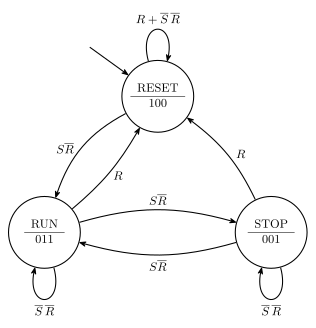
Figure 12: The stopwatch controller when its inputs are edges: S is a push of start/stop and R is a release of reset. Each state shows its name over its outputs C T D. A push of S starts the count from RESET, and after that alternates between RUN and STOP. A release of R returns to RESET from anywhere, and R is written alone on those arrows because it wins if both events arrive together. With nothing happening every state loops back to itself.
Against the four questions:
- Pushed and released. Only one edge of each button is an input, so the other edge does nothing. Letting go of S is not an event, and neither is pushing R.
- Held down. A held button produces no more edges, so nothing more happens.
- Both at once. With both buttons held, nothing happens. Letting go of R resets, whether S is still down or not, and letting go of S is not an event. If a push of S and a release of R arrive in the same step, the arrows for S are labelled \(S\overline{R}\) and the arrows for R are labelled \(R\) alone, so the reset wins.
This is the design that fits interrupts, because an edge on a pin is exactly what an external interrupt reports.
With levels as inputs
If R is instead the level of the reset button, 1 for as long as it is down, the machine has to do the waiting itself. Going straight to RESET when R becomes 1 would reset on the push. So each of RUN and STOP gets a partner state that means “reset is being held”, and the move to RESET happens when R goes back to 0.
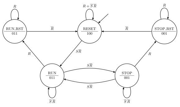
Figure 13: The controller when R is the level of the reset button, 1 while it is held down. Two states are added. While reset is held the machine waits in RUN_RST or STOP_RST, with the same outputs as the state it came from, so the stopwatch carries on exactly as it was. Only when the button is let go does it move to RESET. S has to be a single push of start/stop, 1 for one step, and it is ignored for as long as R is 1.
- Reset on release. RUN to RUN_RST on \(R\), wait there while \(R\) stays 1, then RUN_RST to RESET on \(\overline{R}\). The same from STOP.
- Held down. RUN_RST and STOP_RST loop on \(R\) for as long as the button is held, and the stopwatch does not change in the meantime: a running count keeps running.
- Both at once. From RUN or STOP, \(R\) takes priority over \(S\). In the waiting states S is not looked at. Whichever order the buttons are let go in, the machine arrives in RESET with nothing pending.
For this to work S has to be an event, 1 for a single step when the button goes down. If S were a raw level too, holding it would flip between RUN and STOP on every step, and it would need waiting states of its own.
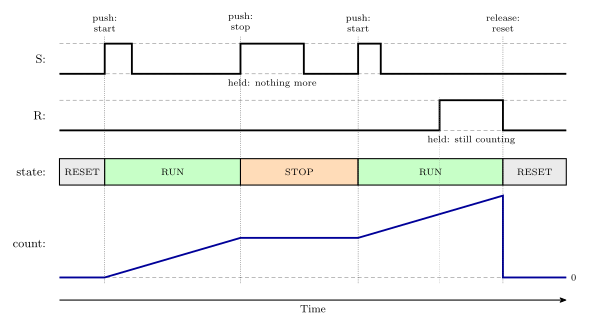
Figure 14: One run of the stopwatch. The count starts at the moment S is pushed and not when it is let go, and each later push of S stops or restarts it. Holding S down for a long time does nothing extra. When R is pushed the count carries on, and the stopwatch clears only at the moment R is let go. In the design with levels as inputs, the stretch where R is held is the waiting state RUN_RST, which has the same outputs as RUN.
Preparation: timer 1 for a 10 ms tick
The stopwatch needs something to happen 100 times a second. Timer/counter 1 does it with a compare match A every 10 ms:
- divide the 8 MHz clock by 8, so the timer counts at 1 MHz;
- clear the count on the compare match (CTC mode), so the match comes round at a steady rate;
- leave the output pins alone.
What goes in OCR1A? From the master formula (avr-timers-and-counters):
\[100 = \frac{8\,000\,000}{8 \times (OCR1A + 1)} \quad\Longrightarrow\quad OCR1A + 1 = 10\,000 \quad\Longrightarrow\quad OCR1A = \mathbf{9999}\]
The register is 16 bits, held as two bytes OCR1AH and OCR1AL. In C it is written as one 16-bit value and the compiler splits it.
What goes in TCCR1A and TCCR1B? Pages 136 to 139 of the datasheet.
| Setting | Bits | |
|---|---|---|
| no output pins | COM1A1:0 = 00, COM1B1:0 = 00 |
all 0 in TCCR1A |
CTC, top in OCR1A |
WGM13:0 = 0100 |
WGM12 in TCCR1B. The other three are 0 |
| clock / 8 | CS12:0 = 010 |
CS11 in TCCR1B |
OCR1A  = 9999;
TCCR1A = 0;
TCCR1B = (1<<WGM12) | (1<<CS11);
Interrupts in C
The global switch. The I bit, bit 7 of the status register SREG, turns all interrupts on or off together. sei() sets it and cli() clears it. In assembly the same two are the instructions sei and cli.
Setting an interrupt up takes five things:
- Set the conditions for the interrupt, such as a timer’s mode and compare value, or which edge of a pin.
- Enable that interrupt by setting its bit in the mask register.
- Clear its flag, in case it is already set from before. A flag is cleared by writing a 1 to it.
- Have a handler for it.
- Turn interrupts on globally with
sei().
The handler is a function with no arguments and no return value, written with the ISR macro:
#include <avr/interrupt.h>

ISR(INT0_vect) {
    /* code that runs when the interrupt happens */
}
The name in the brackets is the interrupt’s source name from the vector table (pages 69 to 70 of the datasheet) with _vect on the end: INT0_vect, TIMER1_COMPA_vect, and ADC_vect for the end of an analog conversion. The full list is in the avr-libc documentation for <avr/interrupt.h>.
The compiler does the rest. In C there is no vector table to write and no registers to save by hand. ISR puts the handler’s address in the table, and the compiled handler saves the registers it uses on the way in and restores them on the way out.
Handlers must be short. While one runs, everything else waits, other interrupts included. A handler records what happened and returns. Printing in a handler is far too slow. The stopwatch’s tick handler does a little more than count, since it also lights the next display digit, but both jobs together take well under a thousand clock cycles out of the 80 000 between ticks.
Shared variables are volatile. A variable that a handler changes and the main program reads must be declared volatile, as in volatile uint8_t count;. Without it the compiler may assume the variable cannot change behind the main program’s back and never read it again (avr-interrupts).
Three checks
What is the handler for timer/counter 1’s compare match A called? The source name in the vector table is TIMER1_COMPA, so the handler is ISR(TIMER1_COMPA_vect).
Of these interrupts, which has the highest priority? TIMER0_COMPA, TIMER0_COMPB, TIMER1_COMPA, TIMER1_COMPB, TIMER2_COMPA, TIMER2_COMPB, USART0_RX, USART0_TX.
Priority goes by position in the vector table, lowest vector number first:
| Source | Vector |
|---|---|
TIMER2_COMPA |
10 |
TIMER2_COMPB |
11 |
TIMER1_COMPA |
14 |
TIMER1_COMPB |
15 |
TIMER0_COMPA |
17 |
TIMER0_COMPB |
18 |
USART0_RX |
21 |
USART0_TX |
23 |
So TIMER2_COMPA. The trap is to expect timer 0 to come first. The table lists the timers in the order 2, 1, 0.
Which pin is INT1? PD3. INT0 is PD2, next to it.
Two worked set-ups
A timer compare match
To run a handler on every compare match A of timer/counter 1:
ISR(TIMER1_COMPA_vect) {
    /* runs on every compare match A */
}

/* in main */
OCR1A  = 9999;                          /* 1: the conditions              */
TCCR1A = 0;
TCCR1B = (1<<WGM12) | (1<<CS11);
TIMSK1 = (1<<OCIE1A);                   /* 2: enable (bit 1 of TIMSK1)    */
TIFR1  = (1<<OCF1A);                    /* 3: clear the flag by writing 1 */
sei();                                  /* 5: interrupts on               */
TIMSK1 is on page 142 of the datasheet and TIFR1 on page 143.
An external interrupt on a rising edge
To run a handler whenever pin INT0 (PD2) goes from 0 to 1:
ISR(INT0_vect) {
    /* runs on every rising edge of PD2 */
}

/* in main */
EICRA = (1<<ISC01) | (1<<ISC00);        /* 1: rising edge                 */
EIMSK = (1<<INT0);                      /* 2: enable                      */
EIFR  = (1<<INTF0);                     /* 3: clear the flag by writing 1 */
sei();                                  /* 5: interrupts on               */
The sense control bits in EICRA choose what counts as a request (avr-interrupts):
ISCn1:0 |
A request is made |
|---|---|
00 |
for as long as the pin is low |
01 |
on any change of the pin |
10 |
on a falling edge |
11 |
on a rising edge |
These registers are on pages 75 and 76 of the datasheet. The register diagrams there label the bits IINT0 and IINTF0, which is a misprint. The names are INT0 and INTF0.
One timer, many timings
Three timer/counters are not enough if each timed thing gets one to itself. A software timer gets round it. One timer interrupt at a fixed interval adds 1 to a global count of the time since reset, and everything else reads that count. Copying the count into a local variable marks the moment something happened, and subtracting two such copies gives a duration, in units of the interrupt period. Code built this way never has to sit in a delay doing nothing (software-timers).
The stopwatch is a first step towards it. Its time is a count of 10 ms ticks, advanced by the tick handler only while the stopwatch is running.
The tasks
- Start from
lab14-1.c.- Fill in the code where indicated, using the register values worked out above.
- Add the controller code from the state diagram.
- Compile and simulate. Put a breakpoint in the handler and make sure it is reached, and check the cycle counter is what it should be.
- Check that it works on the board.
- Start from
lab14-2.c. Make start/stop a push button on an external interrupt: a rising edge onINT0(pin D2). Set up the edge, enable the interrupt and clear the flag. Compile, simulate, download and test. - Add a reset button: an interrupt on the falling edge of
INT1(pin D3). - Extension: after 9.9 s, show whole seconds (10, 11, 12, and so on) instead of wrapping round.
Working — Exercise 1
lab14-1.c and lab14-2.c come with gaps to fill in. These are complete programs that do the job, to compare against.
Wiring. The seven-segment display is on port A with its digit select CC on PD0, as in Lab 12. Start/stop is on PD2 and reset on PD3, which are the pins the later exercises need. The buttons read 1 while pressed.
The design. The timer handler runs every 10 ms. It advances the count while the stopwatch is running and lights one of the two digits. The main loop is the controller of Figure 13. It reads the buttons as levels once per tick, steps the state machine, and sets the three outputs from the state.
#include <avr/io.h>
#include <avr/interrupt.h>

/* controller states */
#define RESET     0
#define RUN       1
#define STOP      2
#define RUN_RST   3       /* running, reset button held */
#define STOP_RST  4       /* stopped, reset button held */

uint8_t seven_seg[10] = { 63,6,91,79,102,109,125,7,127,111 };

/* shared between main and the handler, so all volatile */
volatile uint16_t count;       /* elapsed time, in hundredths of a second */
volatile uint8_t  timing;      /* T: the count advances while this is 1   */
volatile uint8_t  showing;     /* D: the digits are lit while this is 1   */
volatile uint8_t  tick;        /* set by the handler every 10 ms          */

/* runs 100 times a second */
ISR(TIMER1_COMPA_vect) {
    static uint8_t left = 0;
    uint8_t tenths;

    if (timing) {
        count++;
        if (count == 1000) {            /* 9.99 s rolls over to 0.00 */
            count = 0;
        }
    }

    /* one digit per tick: seconds on the left, tenths on the right */
    tenths = count / 10;                /* 0 to 99 */
    left = !left;
    if (!showing) {
        PORTA = 0;
    } else if (left) {
        PORTA = seven_seg[tenths / 10] | 0x80;     /* with the decimal point */
        PORTD |= (1<<0);
    } else {
        PORTA = seven_seg[tenths % 10];
        PORTD &= ~(1<<0);
    }

    tick = 1;
}

int main(void) {
    uint8_t state = RESET;
    uint8_t s, r, s_before = 0, pushed;

    DDRA = 0xFF;                        /* segments                        */
    DDRD = (1<<0);                      /* CC out; PD2 (S) and PD3 (R) in  */

    /* timer 1: compare match A every 10 ms */
    OCR1A  = 9999;
    TCCR1A = 0;
    TCCR1B = (1<<WGM12) | (1<<CS11);

    TIMSK1 = (1<<OCIE1A);               /* enable the compare match A interrupt */
    TIFR1  = (1<<OCF1A);                /* clear its flag by writing 1          */
    sei();                              /* interrupts on                        */

    while (1) {
        if (tick) {                     /* once per 10 ms */
            tick = 0;

            s = (PIND >> 2) & 1;
            r = (PIND >> 3) & 1;
            pushed = s && !s_before;    /* S has gone down since the last tick */
            s_before = s;

            /* next state */
            switch (state) {
            case RESET:
                if (pushed && !r) { state = RUN; }
                break;
            case RUN:
                if (r)           { state = RUN_RST; }
                else if (pushed) { state = STOP; }
                break;
            case STOP:
                if (r)           { state = STOP_RST; }
                else if (pushed) { state = RUN; }
                break;
            case RUN_RST:
            case STOP_RST:
                if (!r) { state = RESET; }
                break;
            }

            /* outputs: they depend on the state alone */
            timing  = (state == RUN || state == RUN_RST);     /* T */
            showing = (state != RESET);                       /* D */
            if (state == RESET) {                             /* C */
                cli();
                count = 0;
                sei();
            }
        }
    }
}
How the code follows the diagram.
- One
caseper state, oneifper arrow. Testingrbeforepushedis what makes reset win when both happen together. A state’s loop back to itself is the case where noiffires. - S as an event.
PINDgives the level of the button, 1 on every pass while it is held. The diagram wants a push. Comparing each reading with the one before,s && !s_before, is true only on the pass where the reading goes from 0 to 1. - R as a level.
ris used as it is read, and the two waiting states turn the level into “act on the release”. - Outputs from the state.
timing,showingand the clearing ofcountare set fromstateand nothing else, which is what makes it a Moore machine. cli()aroundcount = 0.countis 16 bits, and an 8-bit processor writes it one byte at a time. Turning interrupts off for those two instructions keeps the handler from running in between and seeing half of the old value with half of the new (software-timers).- Reading the buttons once per tick also deals with contact bounce. A button’s contacts chatter for a few milliseconds as they close. With readings 10 ms apart, at most one of them can land in the chatter, so a push is still seen as a single change from 0 to 1.
In the simulator. Put a breakpoint on the first line of the handler and run. Each time the program stops there, the cycle counter should have advanced by 80 000, which is 10 ms at 8 MHz. If the breakpoint is never reached, one of the five set-up steps is missing. If the interval is wrong, check OCR1A and the prescaler bits.
Working — Exercises 2 and 3
With the buttons on external interrupts the hardware finds the edges, so the controller becomes the three-state machine of Figure 12 and each button’s handler is one of its inputs.
#include <avr/io.h>
#include <avr/interrupt.h>

#define RESET  0
#define RUN    1
#define STOP   2

uint8_t seven_seg[10] = { 63,6,91,79,102,109,125,7,127,111 };

volatile uint16_t count;              /* hundredths of a second */
volatile uint8_t  state = RESET;

/* every 10 ms */
ISR(TIMER1_COMPA_vect) {
    static uint8_t left = 0;
    uint8_t tenths;

    if (state == RUN) {               /* T */
        count++;
        if (count == 1000) {
            count = 0;
        }
    }

    tenths = count / 10;
    left = !left;
    if (state == RESET) {             /* D is 0 */
        PORTA = 0;
    } else if (left) {
        PORTA = seven_seg[tenths / 10] | 0x80;
        PORTD |= (1<<0);
    } else {
        PORTA = seven_seg[tenths % 10];
        PORTD &= ~(1<<0);
    }
}

/* Exercise 2. Start/stop: a rising edge on INT0 (PD2), the push */
ISR(INT0_vect) {
    if (state == RUN) {
        state = STOP;
    } else {
        state = RUN;                  /* from RESET or from STOP */
    }
}

/* Exercise 3. Reset: a falling edge on INT1 (PD3), the release */
ISR(INT1_vect) {
    state = RESET;
    count = 0;                        /* C */
}

int main(void) {
    DDRA = 0xFF;
    DDRD = (1<<0);

    OCR1A  = 9999;
    TCCR1A = 0;
    TCCR1B = (1<<WGM12) | (1<<CS11);
    TIMSK1 = (1<<OCIE1A);
    TIFR1  = (1<<OCF1A);

    /* INT0 on a rising edge  (ISC01:0 = 11)
       INT1 on a falling edge (ISC11:0 = 10) */
    EICRA = (1<<ISC01) | (1<<ISC00) | (1<<ISC11);
    EIMSK = (1<<INT0) | (1<<INT1);
    EIFR  = (1<<INTF0) | (1<<INTF1);

    sei();

    while (1) {
        /* nothing to do: the handlers do all the work */
    }
}
For Exercise 2 on its own, leave out the INT1 handler and the ISC11, INT1 and INTF1 bits.
Points to notice.
- The main loop is empty. Nothing polls the buttons. The processor is only interrupted when something happens.
- Push and release come from the edge chosen. Start/stop uses the rising edge, so it acts as the button goes down. Reset uses the falling edge, so it acts as the button comes up. Holding either one down produces no further edges, and so no further interrupts.
- No
cli()roundcount = 0this time. Inside a handler interrupts are already off, so the timer handler cannot run in the middle of it. - Both at once. If both flags are set together,
INT0has the lower vector and runs first, thenINT1runs and resets. Reset wins, as the diagram says it should. - Why these two pins.
INT0andINT1are fixed to PD2 and PD3. The buttons have to be wired there. - Bounce shows up here. An edge interrupt responds to every edge, and a bouncing contact makes several, in both directions. A bouncing push of S can start and stop the stopwatch at once, and so can a bouncing release, which makes rising edges too. A bouncing push of R makes falling edges, so the reset can happen on the push instead of the release. A cure is to keep a count of ticks that never stops (software-timers) and ignore an edge that comes within a few ticks of the last one on the same button.
Working — Exercise 4
To carry on past 9.9 s, the count has to run further and the display has to change what it shows. count is in hundredths of a second and is 16 bits wide, so it can go up to 99.99 s without any change of type.
In the timer handler, let the count run to 100 seconds:
    if (state == RUN) {
        count++;
        if (count == 10000) {          /* 99.99 s rolls over to 0.00 */
            count = 0;
        }
    }
and choose the two digits by range. This replaces tenths and the two lines that use it:
    uint8_t l, r;

    if (count < 1000) {                /* under 10 s: seconds and tenths */
        l = seven_seg[count / 100] | 0x80;
        r = seven_seg[(count / 10) % 10];
    } else {                           /* 10 s and over: whole seconds   */
        l = seven_seg[count / 1000];
        r = seven_seg[(count / 100) % 10];
    }

    left = !left;
    if (state == RESET) {
        PORTA = 0;
    } else if (left) {
        PORTA = l;
        PORTD |= (1<<0);
    } else {
        PORTA = r;
        PORTD &= ~(1<<0);
    }
count |
Time | Left digit | Right digit | Shows |
|---|---|---|---|---|
| 0 | 0.00 s | count / 100 = 0, with point |
(count / 10) % 10 = 0 |
0.0 |
| 990 | 9.90 s | 9, with point | 9 | 9.9 |
| 1000 | 10.00 s | count / 1000 = 1 |
(count / 100) % 10 = 0 |
10 |
| 1234 | 12.34 s | 1 | 2 | 12 |
| 9999 | 99.99 s | 9 | 9 | 99 |
The decimal point is what tells the two ranges apart on the display: 9.9 is followed by 10.
See also
- avr-interrupts — the vector table, flags and masks, handlers in C,
volatile, priority, external interrupts - polling-and-interrupts — why interrupts, and what the processor does when one arrives
- software-timers — one timer interrupt, many timings, and no busy waiting
- avr-timers-and-counters — CTC mode and the master formula
- state-machines — Moore machines and state diagrams
- week9-lab-avr-pwm — Lab 13
- week10-lab-adc-and-spi — Lab 16: the A/D converter and the SPI port
- week8-lab-avr-timers — Lab 12: display multiplexing
- 2026-09-21-interrupts — Lecture 17
- seven-segment-display · c-preprocessor-and-avr-headers
Lab 13 — AVR PWM
Learning Lab 13: generating pulse width modulation from the timer/counters. Two programs come out of it. The first fades two LEDs with timer/counter 0, and the second plays a tone on a piezo buzzer with timer/counter 1, with push buttons changing its pitch and its duty cycle. The lab assumes Lab 12 (week8-lab-avr-timers). The ideas are in pulse-width-modulation and avr-timers-and-counters.
Facts to have ready
Five things the lab takes for granted, as quick checks.
| Question | Answer |
|---|---|
| How many timer/counters does the ATmega324A have? | 3 |
| What is the clock frequency? | 8 MHz |
| How wide is each timer/counter? | timer 0 is 8-bit, timer 1 is 16-bit, timer 2 is 8-bit |
| What is the largest value each can hold? | timers 0 and 2: \(2^8 - 1 = 255\). Timer 1: \(2^{16} - 1 = 65535\) |
Which pin is OC0B? |
PB4 (OC0A is PB3) |
Fast PWM on timer/counter 0
The duty cycle of a waveform is the fraction of each period for which it is high. A pin toggled in CTC mode, as in Lab 12, is high for exactly half of every cycle, a duty cycle of 50 %, and nothing about it can be adjusted except the frequency. PWM is what makes the duty cycle adjustable.
In fast PWM the count, held in TCNT0, is a sawtooth: it climbs from 0 to a top value and drops back to 0. An output-compare register sets a level somewhere on the ramp. The output pin changes where the count crosses that level, and changes back when the count wraps. Moving the level moves the crossing, and that changes how much of each period the pin is high.
The waveform generation mode bits choose among all of a timer’s modes: normal, CTC and the PWM modes. Timer 0 has two fast PWM modes:
WGM02:0 |
Top of the count | Compare registers free for PWM | Frequency set by |
|---|---|---|---|
011 (mode 3) |
255, fixed | OCR0A and OCR0B: two PWM outputs |
the prescaler only |
111 (mode 7) |
the value in OCR0A |
OCR0B only: one PWM output |
the prescaler and OCR0A |
Four things apply in both modes:
- The waveform appears on the output-compare pin only if that pin’s DDR bit is set to make it an output.
- The output can be non-inverting or inverting, chosen by the compare output mode bits.
- The prescaler sets how fast the count climbs, and so the slope of the ramp.
- The output-compare registers are double buffered. A new value written to one does not take effect until the next cycle begins, so a pulse is never cut short halfway through.
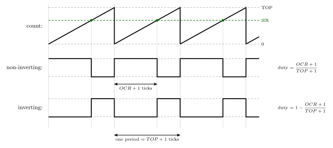
Figure 15: Fast PWM, one compare value, both polarities. The count ramps from 0 to TOP and wraps. In non-inverting mode the pin is set at the wrap and cleared at the compare match, so it is high for the first \(OCR + 1\) ticks of each period. In inverting mode it is the exact opposite, low until the match and high until the wrap. The two outputs are complements, and their duty cycles add up to 1.
The two formulas
Frequency: the master formula (avr-timers-and-counters).
\[f_{event} = \frac{f_{clk\_I/O}}{N \cdot (TOP + 1)}\]
\(f_{clk\_I/O}\) is 8 MHz, \(N\) is the prescaler, and \(TOP\) is either the largest value the register can hold or the value in OCRnA, depending on the mode. What “the event” is depends on the use:
| Use | \(f_{event}\) is |
|---|---|
| a pin set to toggle | how often the pin toggles. The waveform is half that frequency, since one cycle needs a rise and a fall |
| PWM | the frequency of falling edges in non-inverting mode, and of rising edges in inverting mode. That is the PWM frequency |
| an interrupt | how often the handler runs |
Duty cycle.
\[d.c._{nin} = \frac{OCRnx + 1}{TOP + 1} \qquad\qquad d.c._{inv} = 1 - \frac{OCRnx + 1}{TOP + 1} = 1 - d.c._{nin}\]
OCRnx is the compare register for the output in question, A or B.
The two formulas pull against each other in the choice of mode:
- When TOP is
OCRnA, the frequency can be set to almost anything, butOCRnAis used up setting it. OnlyOCRnBgives a meaningful duty cycle. - When TOP is a fixed constant (
0xFFfor the 8-bit timers, with several choices for the 16-bit timer), bothOCRnAandOCRnBgive a duty cycle. But the frequency can then be changed only through the prescaler, or for timer 1 through the choice of constant.
Timer 0’s control bits
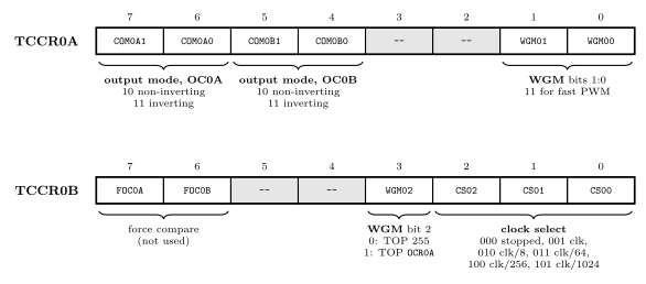
Figure 16: Where timer/counter 0’s settings live. The compare output mode bits come in two pairs, one for each output pin, and both pairs are in TCCR0A. The waveform generation mode is one three-bit number split across the two registers, with its low two bits in TCCR0A and its top bit in TCCR0B. The clock select bits choose the prescaler, and while they are 000 the timer is stopped. Grey cells are unused.
These are on pages 109 to 113 of the datasheet. Clock select 110 and 111 take the clock from the T0 pin instead of the prescaler, which is how Lab 12 counted button presses. The compare output modes in fast PWM:
COM0x1:0 |
The pin OC0x |
|---|---|
00 |
is disconnected from the timer: an ordinary port pin |
01 |
OC0A toggles at each compare match, in mode 7 only. Not used for OC0B |
10 |
non-inverting: cleared at the compare match, set at the wrap |
11 |
inverting: set at the compare match, cleared at the wrap |
Delay macros
#define F_CPU 8000000UL
#include <util/delay.h>
With these two lines, the macros _delay_ms() and _delay_us() are available. Each takes a constant number and makes the CPU do nothing for that many milliseconds or microseconds.
_delay_ms(10); /* do nothing for 10 ms */F_CPU has to be defined before the include, because the macros work out how many instructions to waste from the clock frequency. If it is missing the header only warns and assumes 1 MHz, and on this board every delay then runs 8 times too short. The macros are documented under <util/delay.h> in avr-libc.
This is busy waiting: the processor is fully occupied counting down and can do nothing else in the meantime. It is fine for a quick experiment and a bad habit for anything bigger. The alternative is a timer keeping time in the background (software-timers).
The tasks
Complete lab13-1.c so that two LEDs fade on and off using PWM, one connected to OC0A and one to OC0B.
- Work out the register values from pages 109 to 113 of the datasheet.
- Build it, download it and test it. Predict which LED starts on and which starts off.
- Change the clock prescaler to CLK/1024 and explain what you see.
Complete lab13-2.c to generate sound on the piezo buzzer using PWM on timer/counter 1.
- Connect the buzzer between
OC1Band ground, and an LED toOC1Bas well so that what is happening can be seen. - Push buttons vary both the frequency and the duty cycle.
- The code uses 32-bit constants such as
105ULin places. Why are they necessary? - Challenge: show the duty cycle, 0 to 99, on the seven-segment display.
Working — Task 1
lab13-1.c comes with gaps to fill in. This is a complete program that does the job, to compare against.
The design. Fast PWM with TOP fixed at 255 (mode 3), because two outputs are needed and the frequency does not matter much. One compare value, level, is swept slowly from 0 up to 255 and back, and written to both compare registers. OC0A is made non-inverting and OC0B inverting, so as one LED brightens the other dims.
The register values.
| Setting | Bits | Value |
|---|---|---|
| fast PWM, TOP = 255 | WGM02:0 = 011 |
WGM01, WGM00 in TCCR0A. WGM02 stays 0 |
OC0A non-inverting |
COM0A1:0 = 10 |
COM0A1 |
OC0B inverting |
COM0B1:0 = 11 |
COM0B1, COM0B0 |
| clock / 64 | CS02:0 = 011 |
CS01, CS00 in TCCR0B |
The PWM frequency is \(8\,000\,000 / (64 \times 256) = 488\ \text{Hz}\), far too fast to see.
#define F_CPU 8000000UL
#include <avr/io.h>
#include <util/delay.h>

int main(void) {
    uint8_t level = 0;      /* compare value: 0 to 255          */
    int8_t  step  = 1;      /* +1 on the way up, -1 on the way down */

    /* OC0A is PB3 and OC0B is PB4: both must be outputs */
    DDRB |= (1<<3) | (1<<4);

    /* Fast PWM with TOP = 255; OC0A non-inverting, OC0B inverting */
    TCCR0A = (1<<COM0A1) | (1<<COM0B1) | (1<<COM0B0)
           | (1<<WGM01) | (1<<WGM00);

    /* Clock / 64.  This starts the timer. */
    TCCR0B = (1<<CS01) | (1<<CS00);

    while (1) {
        OCR0A = level;
        OCR0B = level;
        _delay_ms(5);                 /* 255 steps of 5 ms: about 1.3 s each way */

        if (level == 255) {
            step = -1;
        } else if (level == 0) {
            step = 1;
        }
        level += step;
    }
}
Which LED starts on? At the start level is 0.
OC0A, non-inverting: duty \(= (0 + 1)/256 \approx 0.4\,\%\). The LED on PB3 starts off.OC0B, inverting: duty \(= 1 - 1/256 \approx 99.6\,\%\). The LED on PB4 starts on.
As level rises the first brightens and the second dims, they cross at half brightness, and at 255 they have swapped. The non-inverting output never reaches exactly 0 %: even with a compare value of 0 the pin is high for one tick in 256.
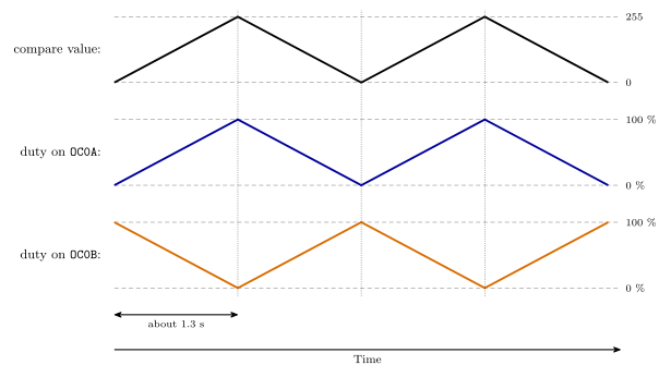
Figure 17: The fade in Task 1. The compare value is swept up from 0 to 255 and back down, about 1.3 seconds each way. The two outputs share that one value but have opposite polarity, so their duty cycles are mirror images: the LED on OC0A is brightest when the value is 255 and the LED on OC0B is brightest when it is 0. The dim end of each is one tick in 256 short of fully off.
With the prescaler at CLK/1024. Change the last register write to
TCCR0B = (1<<CS02) | (1<<CS00); /* clock / 1024 */The PWM frequency drops to \(8\,000\,000 / (1024 \times 256) = 30.5\ \text{Hz}\). The eye can follow that. The LEDs flicker instead of dimming smoothly, most obviously when the duty cycle is low and the LED is giving short flashes thirty times a second. The fade itself takes just as long as before, because _delay_ms(5) sets its speed, not the timer. The duty cycle is unchanged as well. Only the PWM frequency has changed, and this is what shows that PWM dims an LED only when it is too fast to see.
The fade also turns into steps. A PWM period is now 32.8 ms, and a new compare value only takes effect at the start of a period, so of the values written every 5 ms only about one in six or seven is ever used.
Working — Task 2
lab13-2.c also comes with gaps. This is a complete program that meets the task.
The design. A tone needs a frequency that can be set freely, so this uses a fast PWM mode in which TOP is OCR1A. That leaves OCR1B for the duty cycle, which is why the buzzer goes on OC1B. Timer 1 is 16 bits wide, so one prescaler setting covers the whole audible range.
| Setting | Bits | Where |
|---|---|---|
fast PWM, TOP = OCR1A |
WGM13:0 = 1111 (mode 15) |
WGM11, WGM10 in TCCR1A; WGM13, WGM12 in TCCR1B |
OC1B non-inverting |
COM1B1:0 = 10 |
COM1B1 in TCCR1A |
| clock / 8 | CS12:0 = 010 |
CS11 in TCCR1B |
With the prescaler at 8 the timer counts at 1 MHz, one tick per microsecond. For a tone of frequency \(f\):
\[\text{period in ticks} = \frac{1\,000\,000}{f} \qquad OCR1A = \text{period} - 1 \qquad OCR1B = \frac{\text{duty} \times \text{period}}{100} - 1\]
The first is the master formula rearranged, and the last is the duty-cycle formula rearranged, with the duty as a percentage. At 200 Hz the period is 5000 ticks, so OCR1A is 4999, and a 50 % duty cycle makes OCR1B 2499.
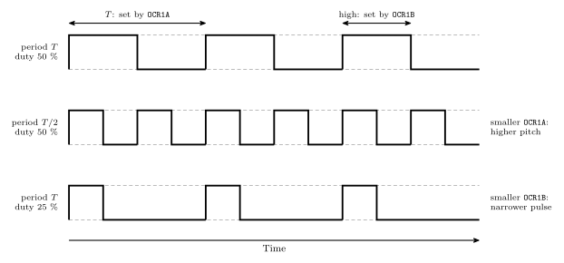
Figure 18: The two settings of Task 2 and what each one changes. OCR1A is the top of the count, so it sets the length of the period and with it the pitch. OCR1B sets how much of each period the pin is high, the duty cycle. Halving the period while keeping the duty cycle at 50 percent gives the middle waveform, an octave higher. Keeping the period and narrowing the pulse to 25 percent gives the bottom one, the same pitch with less energy.
The program. Four push buttons on port C: PC0 raises the frequency and PC1 lowers it, PC2 raises the duty cycle and PC3 lowers it. The buttons read 1 while pressed, and each press counts once.
#define F_CPU 8000000UL
#include <avr/io.h>
#include <util/delay.h>

uint16_t freq = 200;     /* Hz                      */
uint8_t  duty = 50;      /* percent, 0 to 99        */

/* Load the timer from freq and duty.  The timer counts at 1 MHz. */
void update_pwm(void) {
    uint16_t period = 1000000UL / freq;                   /* ticks per cycle */
    uint16_t width  = (duty * (uint32_t)period) / 100;    /* ticks high      */

    OCR1A = period - 1;                 /* TOP: sets the frequency           */
    if (width == 0) {
        TCCR1A &= ~(1<<COM1B1);         /* 0 %: hand the pin back to PORTD   */
    } else {
        OCR1B = width - 1;              /* high for OCR1B + 1 ticks          */
        TCCR1A |= (1<<COM1B1);
    }
}

int main(void) {
    uint8_t now, before = 0, pressed;

    DDRD |= (1<<4);                     /* OC1B is PD4                       */
    PORTD &= ~(1<<4);                   /* low whenever the timer lets go    */
    DDRC &= 0xF0;                       /* PC0 to PC3 are the buttons        */

    update_pwm();                       /* load OCR1A and OCR1B first        */

    /* Fast PWM with TOP = OCR1A (mode 15), OC1B non-inverting, clock / 8 */
    TCCR1A = (1<<COM1B1) | (1<<WGM11) | (1<<WGM10);
    TCCR1B = (1<<WGM13) | (1<<WGM12) | (1<<CS11);   /* this starts the timer */

    while (1) {
        now = PINC & 0x0F;
        pressed = now & ~before;        /* buttons that have just gone down  */
        before = now;

        if (pressed & (1<<0)) { freq = freq * 105UL / 100; }   /* up 5 %    */
        if (pressed & (1<<1)) { freq = freq * 100UL / 105; }   /* down 5 %  */
        if (pressed & (1<<2)) { duty = (duty >= 95) ? 99 : duty + 5; }
        if (pressed & (1<<3)) { duty = (duty == 99) ? 95 : (duty >= 5 ? duty - 5 : 0); }

        if (freq < 20)    { freq = 20; }
        if (freq > 10000) { freq = 10000; }

        if (pressed) {
            update_pwm();
        }
        _delay_ms(10);                  /* ride out contact bounce           */
    }
}
Why the UL constants are needed. On the AVR an int is 16 bits. In freq * 105 / 100 both operands would be 16-bit, the multiplication would be done in 16 bits, and the result would overflow as soon as freq passed \(65535 / 105 = 624\) Hz. A tone of 1000 Hz would give \(105\,000\), which wraps to 39 464, and the “5 % higher” frequency would come out as 394 Hz. Writing 105UL makes the constant an unsigned long, 32 bits, so the compiler does the whole multiplication in 32 bits and only the final result is narrowed back to 16. The suffix matters on the constants that would fit in an int, 105UL and 100UL. On 1000000UL it is harmless but not needed, since a number too big for an int is given a 32-bit type anyway. The (uint32_t) cast in the width calculation does the same job as the suffix, where duty * period can reach nearly five million (c-language-basics: an int is 16 bits on the AVR).
Other points.
- The pin still needs
DDRD. The timer decides the pin’s value. The DDR bit decides whether the pin drives anything. - Changing the values while it runs. Each compare register is double buffered: a new value is held back and loaded when the count wraps, so a pulse already under way is not disturbed. The two registers are written a few instructions apart, so at worst one period uses the new
OCR1Awith the oldOCR1B, which is one odd cycle of a tone. Disconnecting the pin for 0 % is not buffered and takes effect at once. - Load the compare registers before starting the timer.
maincallsupdate_pwm()first, so the timer never runs withOCR1Astill at 0. - 0 % is a special case. In non-inverting fast PWM the pin is high for
OCR1B + 1ticks, which is at least one. For a true 0 % the function disconnects the pin from the timer, and the port bit, set to 0, holds it low. - The lowest frequency. With the prescaler at 8, the longest period is 65 536 ticks, about 15 Hz. The program stops at 20 Hz.
- What duty cycle does to a tone. The pitch depends only on the frequency. The duty cycle changes the loudness and the character of the sound, and is loudest near 50 %. On the LED it shows as brightness.
Challenge: the duty cycle on the seven-segment display. The two-digit multiplexing of Lab 12 fits into the main loop, which already comes round every 10 ms. Show one digit per pass: the display is on port A, with the digit select CC on PD0 (seven-segment-display).
uint8_t seven_seg[10] = { 63,6,91,79,102,109,125,7,127,111 };
uint8_t left = 0;

/* in main, before the loop */
DDRA = 0xFF;
DDRD |= (1<<0);

/* in the loop, once per pass */
if (left) {
    PORTA = seven_seg[duty / 10];     /* tens  */
    PORTD |= (1<<0);                  /* CC = 1: left digit  */
} else {
    PORTA = seven_seg[duty % 10];     /* ones  */
    PORTD &= ~(1<<0);                 /* CC = 0: right digit */
}
left = !left;
Each digit is refreshed 50 times a second, which is just fast enough to look steady. Shortening the delay to 5 ms makes it more comfortable.
Next
Lab 14 has a preparation task, to be done before the session (week9-lab-avr-interrupts).
See also
- pulse-width-modulation — duty cycle, average value, the fast PWM modes and their formulas
- avr-timers-and-counters — the timers, their registers, the prescaler and the master formula
- week8-lab-avr-timers — Lab 12: the control registers bit by bit, and display multiplexing
- software-timers — keeping time without busy waiting
- 2026-09-17-pulse-width-modulation — Lecture 16
- seven-segment-display · bit-masking · c-language-basics · avr-io-ports
Reference material
Analog to Digital Conversion
Turning a voltage into a number the processor can use. A digital input pin only distinguishes 0 from 1. An analog to digital converter (ADC) reports how big a voltage is, to a fixed number of bits. First met in 2026-09-24-serial-io, and used to read a joystick in week10-lab-adc-and-spi.
What a converter does
An ADC takes an input voltage between 0 and a maximum, the reference voltage \(V_{ref}\), and produces an unsigned integer in proportion to it. Zero volts gives 0, and a voltage just under \(V_{ref}\) gives the largest value the result can hold.
The number of bits in the result is the converter’s resolution. With \(n\) bits there are \(2^n\) possible results, 0 to \(2^n - 1\):
| Resolution | Results | Range |
|---|---|---|
| 8 bits | 256 | 0 to 255 |
| 10 bits | 1024 | 0 to 1023 |
| 12 bits | 4096 | 0 to 4095 |
From voltage to number
The converter divides the range from 0 to \(V_{ref}\) into \(2^n\) equal steps and reports which step the input is on. For a 10-bit converter:
\[\text{result} = \left\lfloor \frac{V_{in}}{V_{ref}} \times 1024 \right\rfloor, \qquad \text{at most } 1023\]
and the size of one step is
\[\frac{V_{ref}}{1024} = \frac{5\ \text{V}}{1024} \approx 4.9\ \text{mV} \quad\text{when } V_{ref} = 5\ \text{V}.\]
| \(V_{in}\) (with \(V_{ref}\) = 5 V) | Result |
|---|---|
| 0 V | 0 |
| 1.25 V | 256 |
| 2.5 V | 512 |
| 3.75 V | 768 |
| 5 V | 1023 |
Two things follow from the staircase in Figure 19.
- The result is rounded down to a step. Every voltage within one step gives the same number, so a result is only known to within one step, 4.9 mV here. More bits means smaller steps.
- The top result is \(2^n - 1\), not \(2^n\). There are 1024 steps numbered from 0, so full scale reads 1023.
Going the other way, a result \(r\) stands for a voltage of about \(r \times V_{ref} / 1024\). A reading of 300 with a 5 V reference is about \(300 \times 4.88\ \text{mV} = 1.46\ \text{V}\).
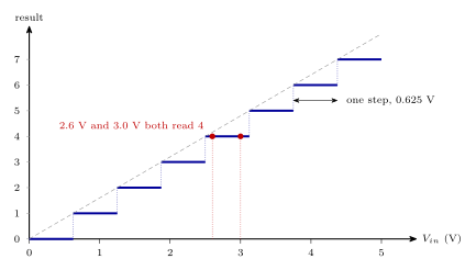
Figure 19: Conversion with a 3-bit converter and a 5 V reference, drawn with few enough steps to see. The input range is cut into \(2^3 = 8\) equal steps of 0.625 V, and the result is the number of the step the input is on, from 0 to 7. Every voltage within a step gives the same result, so 2.6 V and 3.0 V both read 4. A 10-bit converter does the same thing with 1024 steps of about 4.9 mV.
The ATmega324A’s converter
- Inputs. The eight port A pins can be used as analog inputs. A pin used this way is not read through
PINA. The result comes from the converter’s own data register,ADC, which is 16 bits wide to hold the 10-bit result. - One at a time. There is a single converter, with an analog multiplexer in front of it that connects one of the pins to it. To read two voltages, such as the two axes of a joystick, select one pin and convert, then select the other and convert.
- Reference. \(V_{ref}\) can be chosen. The course uses the supply, \(V_{cc} = 5\ \text{V}\).
- Resolution. 10 bits: results from 0 to 1023.
- Time. A conversion is not instant. It takes up to 3200 clock cycles, which is 0.4 ms with the 8 MHz clock. The converter can be run faster at the cost of accuracy.
Because a conversion takes thousands of clock cycles, starting one and getting the answer are separate moments. Between them the program either waits and checks whether the converter has finished, or does something else and lets the converter raise an interrupt when it has (polling-and-interrupts). The interrupt has its own vector, written ISR(ADC_vect) in C (avr-interrupts).
Worked: a joystick
A joystick gives two voltages between 0 and 5 V, one for left-right and one for up-down. Pushed three-quarters of the way right and a quarter of the way up, it gives 3.75 V and 1.25 V, which convert to 768 and 256. Centred, each axis is near 2.5 V and reads near 512. Each reading takes its own conversion, so the two numbers are from slightly different moments.
Inside, each axis is a potentiometer between 5 V and ground, and the stick moves its wiper, so the wiper’s voltage follows the stick from one side to the other (io-board).
Worked: where is the stick?
A joystick’s reading is easiest to interpret measured from the centre. Half of 1023 is 511.5, so 511 and 512 do equally well as the centre. Taking 511 on both axes,
\[\Delta x = x - 511, \qquad \Delta y = y - 511,\]
the direction of the stick is the angle \(\tan^{-1}(\Delta y / \Delta x)\), measured anticlockwise from straight right and put in the right quadrant by the signs, and how far it is pushed is \(\sqrt{\Delta x^2 + \Delta y^2} / 511\) of full deflection.
- (511, 0): \(\Delta x = 0\), \(\Delta y = -511\). Straight down, all the way.
- (614, 689): \(\Delta x = 103\), \(\Delta y = 178\). The angle is \(\tan^{-1}(178/103) = 60^\circ\), and the distance is \(\sqrt{103^2 + 178^2} = 206\), which is \(206 / 511 = 40\,\%\) of full deflection.
The readings themselves are never negative: \(\Delta x\) and \(\Delta y\) are what a program works out, not what the converter reports. And the centre is only roughly 511, since a real stick at rest sits a few counts to one side, so a program tests against a margin, as in week10-lab-adc-and-spi.
The registers
A program runs the converter through three registers, counting the 16-bit result as one:
| Register | Holds |
|---|---|
ADMUX |
which reference, which input, and how the result is lined up |
ADCSRA |
on and off, start, the finished flag and its interrupt enable, and the clock prescaler |
ADC, as ADCH and ADCL |
the result |
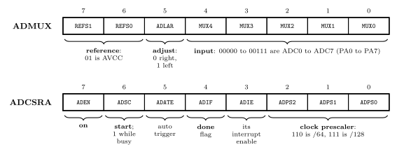
Figure 20: The converter’s two control registers, with their bits grouped by what they do. In ADMUX the top two bits choose the reference voltage, bit 5 chooses whether the 10-bit result is lined up at the right or the left of its 16-bit register, and the bottom five choose the input pin. In ADCSRA bit 7 switches the converter on, bit 6 starts a conversion and stays 1 while it runs, bit 4 is the flag set when a result is ready and bit 3 its interrupt enable, and the bottom three bits divide the system clock down to the converter’s own clock.
ADMUX: what to convert
REFS1 |
REFS0 |
Reference voltage |
|---|---|---|
| 0 | 0 | whatever is on the AREF pin |
| 0 | 1 | AVCC, the converter’s supply, 5 V on the lab boards |
| 1 | 0 | an internal 1.1 V |
| 1 | 1 | an internal 2.56 V |
ADLAR, ADC left adjust result, is 0 for a result lined up at the right of the 16-bit register, so that it reads as a number from 0 to 1023. Set to 1, it is lined up at the left instead (below).MUX4:0picks the input.00000to00111are the pins ADC0 to ADC7, which are PA0 to PA7, each on its own. The other codes select differential pairs of pins and two internal test voltages, which the course does not use.
Worked: the value for ADC1
AVCC as the reference, right adjusted, input ADC1:
\[\underbrace{01}_{\texttt{REFS1:0}}\ \underbrace{0}_{\texttt{ADLAR}}\ \underbrace{00001}_{\texttt{MUX4:0}} = \texttt{0100 0001} = \texttt{0x41}\]
In C, ADMUX = (1<<REFS0) | 1;. Writing the register replaces all eight bits, so the reference bits have to be included every time the input is changed. ADMUX = 1; alone would select ADC1 with the AREF pin as the reference, which on a board with nothing connected to AREF gives meaningless results.
ADCSRA: control and status
| Bit | Name | |
|---|---|---|
| 7 | ADEN |
enable: 1 switches the converter on. Nothing happens without it |
| 6 | ADSC |
start conversion: write a 1 to start one. It reads 1 while the conversion runs and drops to 0 when the result is ready |
| 5 | ADATE |
auto trigger: start conversions automatically, for example one after another. Left 0 here |
| 4 | ADIF |
interrupt flag: set when a conversion finishes. Cleared by writing a 1 to it, or by the hardware when the interrupt is taken |
| 3 | ADIE |
interrupt enable for that flag |
| 2–0 | ADPS2:0 |
prescaler: what the system clock is divided by to make the ADC clock |
ADPS2:0 |
000 | 001 | 010 | 011 | 100 | 101 | 110 | 111 |
|---|---|---|---|---|---|---|---|---|
| Divide by | 2 | 2 | 4 | 8 | 16 | 32 | 64 | 128 |
| ADC clock at 8 MHz | 4 MHz | 4 MHz | 2 MHz | 1 MHz | 500 kHz | 250 kHz | 125 kHz | 62.5 kHz |
ADEN and the prescaler are set once. ADSC is set for every conversion.
The result: ADCH and ADCL
The 10-bit result sits in a 16-bit register made of two bytes, ADCH and ADCL. ADLAR decides where.
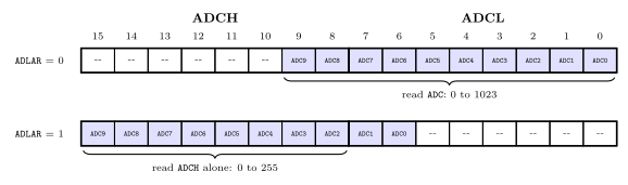
Figure 21: Where the 10 result bits go in ADCH:ADCL. Right adjusted, with ADLAR = 0, bits 9 and 8 are the bottom two bits of ADCH and the rest fill ADCL, so the 16-bit register reads as a number from 0 to 1023 and the six unused bits are 0. Left adjusted, with ADLAR = 1, the result starts at the top, so ADCH on its own holds the top 8 bits, a result from 0 to 255 for a program that does not need all 10.
- Read the low byte first. Reading
ADCLlocks the register, so that a conversion finishing in between cannot replace one byte and not the other, and readingADCHunlocks it. The order isADCL, thenADCH. - In C, read
ADC. The header definesADCas the 16-bit register, and the compiler reads the two bytes in the right order. - Left adjusted,
ADCHalone will do. WithADLAR= 1 the top 8 bits are all inADCH, and readingADCHby itself is allowed. It gives an 8-bit result, steps of about 20 mV with a 5 V reference.
The ADC clock
The converter has its own clock, made by dividing the system clock with the prescaler in ADCSRA. For the full 10 bits of precision, the ADC clock must be between 50 kHz and 200 kHz. A faster clock gives a quicker conversion with fewer accurate bits, which is the trade between accuracy and speed.
A conversion takes 13 ADC clock cycles. The first one after ADEN is set takes 25, because the analog circuits have to settle. At the slowest setting, the system clock divided by 128, that first conversion is \(25 \times 128 = 3200\) system clock cycles, 0.4 ms at 8 MHz, which is the “up to 3200 clock cycles” above.
Worked: choosing the prescaler
With the 8 MHz system clock, the ADC clock is \(8\ \text{MHz} / N\). For it to lie between 50 and 200 kHz,
\[\frac{8\ \text{MHz}}{200\ \text{kHz}} \le N \le \frac{8\ \text{MHz}}{50\ \text{kHz}} \quad\Longrightarrow\quad 40 \le N \le 160.\]
Of the settings on offer, 64 (125 kHz) and 128 (62.5 kHz) are in range. Either is right. 64 is the faster of the two: a conversion takes \(13 \times 64 = 832\) system cycles, 104 µs.
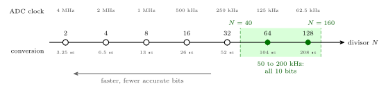
Figure 22: The prescaler settings against the window for full precision. Each setting divides the 8 MHz system clock, giving the ADC clock above the axis and the time for one 13-cycle conversion below it. Only the shaded band, an ADC clock from 50 to 200 kHz, gives all 10 bits. That band is a divisor from 40 to 160, and the two settings inside it are 64 and 128. Settings to the left are faster but less accurate.
A conversion, step by step
- Choose the reference and the input in
ADMUX. - Switch on the converter and set its clock:
ADENand the prescaler bits inADCSRA. Once is enough. - Start a conversion by setting
ADSC. - Wait until it has finished.
ADSCreads 1 until then, and at the end the hardware clears it and setsADIF. - Read the result from
ADC.
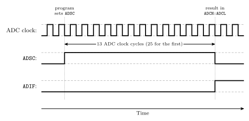
Figure 23: One conversion against time. The program writes a 1 to ADSC and the conversion starts. ADSC stays at 1 for the 13 cycles of the ADC clock that the conversion takes, 25 for the first one after the converter is switched on. At the end the hardware puts ADSC back to 0, sets the flag ADIF and leaves the new result in ADCH:ADCL. A program can wait for either bit, or enable the interrupt and be told.
By polling. Wait for ADSC to drop:
#include <avr/io.h>
#include <stdint.h>

uint16_t adc_read(uint8_t channel) {
    ADMUX = (1<<REFS0) | channel;     /* AVCC, right adjusted, this input */
    ADCSRA |= (1<<ADSC);              /* start                             */
    while (ADCSRA & (1<<ADSC)) { }    /* busy while ADSC reads 1           */
    return ADC;                       /* ADCL, then ADCH                   */
}

int main(void) {
    uint16_t x, y;

    ADCSRA = (1<<ADEN) | (1<<ADPS2) | (1<<ADPS1);   /* on, 8 MHz / 64 = 125 kHz */
    while (1) {
        x = adc_read(0);
        y = adc_read(1);
        (void)x; (void)y;
    }
}
Waiting on ADSC needs no clearing up afterwards. Waiting on ADIF works too, but the flag stays set until a 1 is written to it, so the program has to clear it before the next conversion.
By interrupt. Set ADIE and write a handler for ADC_vect (avr-interrupts). The handler here collects each result and starts the next conversion, so the converter runs continuously and the main program reads the latest value whenever it wants one:
#include <avr/io.h>
#include <avr/interrupt.h>
#include <stdint.h>

volatile uint16_t latest;             /* the newest result */

ISR(ADC_vect) {
    latest = ADC;                     /* ADIF is cleared as the handler starts */
    ADCSRA |= (1<<ADSC);              /* start the next conversion             */
}

int main(void) {
    uint16_t x;

    ADMUX  = (1<<REFS0);                                      /* AVCC, ADC0 */
    ADCSRA = (1<<ADEN) | (1<<ADIE) | (1<<ADPS2) | (1<<ADPS1); /* / 64       */
    sei();
    ADCSRA |= (1<<ADSC);              /* the first conversion */

    while (1) {
        cli();                        /* a 16-bit copy must not be split */
        x = latest;
        sei();
        /* ... use x ... */
        (void)x;
    }
}
latest is two bytes, so the main program copies it with interrupts off, for the reason in software-timers.
Changing input. A change to ADMUX during a conversion only takes effect when that conversion has finished. Change the input between conversions, as adc_read does.
Common mistakes
- Expecting 1024 at full scale. The largest 10-bit result is 1023.
- Forgetting the reference. The same result means a different voltage with a different \(V_{ref}\). A result is a fraction of the reference.
- Treating the result as exact. It is the step the voltage was on, good to one step.
- Expecting two inputs to be read together. One converter, one input at a time.
- Using the result the instant a conversion is started. It is not ready for up to 0.4 ms.
- Forgetting
ADEN. SettingADSCon a converter that is switched off starts nothing. - Losing the reference bits.
ADMUX = 1;selects ADC1 but also setsREFS1:0to00, the AREF pin. Keep(1<<REFS0)in every write. - A prescaler outside the window. At 8 MHz only 64 and 128 put the ADC clock between 50 and 200 kHz. Anything faster gives fewer good bits.
- Reading
ADCHbeforeADCL. ReadingADCLlocks the result untilADCHis read. Read the 16-bitADCin C and the order is right. - Expecting negative readings. The result is unsigned, 0 to 1023. A joystick’s offset from its centre is something the program works out by subtracting.
- Loading the input. An LED, or the pin’s own pull-up resistor switched on through
PORTA, draws current from the voltage being measured and changes it. A potentiometer’s wiper in particular cannot supply current without its voltage moving.
See also
- 2026-09-24-serial-io — Lecture 18, where the converter is introduced
- week10-lab-adc-and-spi — Lab 16: the prescaler and
ADMUXworked, reading a joystick, and four programs that use it - io-board — the joystick module and its pins
- avr-io-ports — the digital side of the same pins
- polling-and-interrupts · avr-interrupts — the two ways to find out a conversion has finished
- avr-architecture — the A/D converter on the block diagram
- binary-number-representations — unsigned integers, and why 10 bits hold 0 to 1023
AVR Architecture
The Atmel AVR: what is on the chip, how the CPU is laid out, and where the fetch-decode-execute cycle happens in it. See cpu-organisation for the generic picture this specialises and avr-instructions for what it executes.
Microcontroller, not microprocessor
Atmel AVR devices are microcontrollers. A microcontroller includes lots of components on one chip:
- CPU
- Memory (RAM)
- Program memory
- Input/output devices
That is the distinction from a microprocessor, which is the CPU alone. An ATmega324A is not a CPU — it contains a CPU, alongside memory and a large collection of peripherals, so that a useful system can be one chip rather than a board full of them.
The AVR CPU
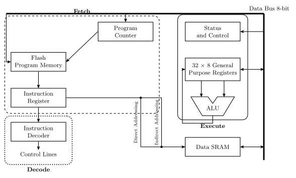
Figure 24: The AVR CPU core, with the three stages of the cycle marked. Fetch (dashed) reads the next instruction from flash under the program counter into the instruction register; decode (dotted) turns it into control lines; execute (solid) runs it over the register file, ALU and status register, with the 8-bit data bus tying everything together. The two lines dropping to the Data SRAM are the direct and indirect addressing routes — both come out of the instruction, which is why they leave from the instruction register. The execute group takes in the status register, the register file and the ALU; the Data SRAM sits outside it.
Reading the diagram as the cycle of fetch-decode-execute-cycle:
| Stage | Blocks involved |
|---|---|
| Fetch | Program Counter → Flash Program Memory → Instruction Register |
| Decode | Instruction Register → Instruction Decoder → Control Lines |
| Execute | General purpose registers → ALU → back to registers, with Status and Control updated |
Because these three groups are largely separate hardware, the AVR overlaps them: while one instruction executes, the next is being fetched. This course calls it a three-stage pipeline. The ATmega164A/324A/644A/1284P datasheet describes the core as “single level pipelining”, i.e. fetch and execute overlapping, which is two stages. Answer three-stage pipeline in the exam, but the datasheet is the authority on the hardware.
The pieces
| Block | Notes |
|---|---|
| Flash program memory | Holds the program. 32 kB on the ATmega324A, and non-volatile — it survives power loss |
| Program Counter | Addresses flash to select the next instruction — the PC of cpu-organisation |
| Instruction Register | Holds the instruction currently being worked on |
| Instruction Decoder | Turns the instruction’s bits into control lines — this is the control unit |
| 32 × 8 general purpose registers | R0–R31, each 8 bits wide, built from flip-flops |
| ALU | 8-bit, so AVR is an 8-bit machine |
| Status and Control | Holds the flags the ALU produces — N, Z, C, V among others |
| Data SRAM | 2 kB, volatile — static RAM, i.e. flip-flops |
| Data bus | 8 bits wide, tying the execute-side blocks together |
Two addressing routes reach the SRAM, drawn as the two vertical paths in Figure 24 — direct addressing (the address is in the instruction) and indirect addressing (the address is in a register). Both leave from the instruction register, because in either case it is the instruction that says which cell is wanted; they differ only in whether it says so with a literal address or with the name of a pointer. Both, and the other two modes, are in addressing-modes.
Four numbers define the chip: the flash is 32 kB and non-volatile; the SRAM is 2 kB, volatile, and made of static flip-flops; the register file is 32 registers, r0…r31, each 8 bits wide and made of flip-flops; and the ALU is 8-bit, which makes the AVR an 8-bit machine.
The register file
General purpose registers (0–31) are quite regular and can be used interchangeably. Two exceptions are worth having by heart:
- A few instructions work on half the registers (r16–r31), because only 4 bits are used to represent the operand in the instruction and \(2^4 = 16\).
LDI,SER,ANDI,ORIandCPIare among them — see avr-instructions. - X, Y and Z are register pairs that double as 16-bit pointers.
X, Y and Z
The top six registers of the file are those three pairs, low byte in the lower-numbered register:
| Pointer | High : Low | Register addresses |
|---|---|---|
| X | R27 : R26 | 0x1B : 0x1A |
| Y | R29 : R28 | 0x1D : 0x1C |
| Z | R31 : R30 | 0x1F : 0x1E |
Two 8-bit registers side by side make a 16-bit address — which is what the data space needs and no single 8-bit register can hold. They are what indirect addressing uses: ld r5, X means “load from wherever X points”, and the instruction only has to name which pointer, so it stays one word (addressing-modes).
The low byte living in the lower-numbered register is the same little-endian convention the AVR uses in memory (memory-models).
Address spaces
The AVR is a Harvard machine — separate address spaces for instructions and data — so 0x0000 names two entirely different locations depending on which space is meant, and the instruction decides.
Data address space — 0x0000 to 0x08FF
| Region | Addresses | Size |
|---|---|---|
| 32 Registers | 0x0000–0x001F |
32 |
| 64 I/O Registers | 0x0020–0x005F |
64 |
| 160 Ext I/O Reg. | 0x0060–0x00FF |
160 |
| Internal SRAM | 0x0100–0x08FF |
2048 bytes (2 kB) |
The register file and all 224 I/O registers are mapped into the data space, ahead of the SRAM. That is what lets lds/sts reach an I/O register by its data address while in/out reach the first 64 by their I/O register number — the two numbering systems differ by exactly the 0x20 the register file occupies. Details in avr-io-ports.
The datasheet draws the SRAM box as 1024/2048/4096/16384 × 8 because the diagram covers the whole ATmega164A/324A/644A/1284P family; the 324A is the 2048 entry, which is what puts the top of the data space at 0x08FF.
Program memory — 0x0000 to 0x3FFF
\(2^{14}\) 16-bit words: 16,384 instruction words = 32,768 bytes = 32 kB. The datasheet splits it into an Application Flash Section and, at the highest addresses, a Boot Flash Section.
0x3FFF \(= 2^{14} - 1\), and the sizing arithmetic — why 32 kB of program memory is 14 address bits rather than 15 — is worked through in memory-models. The short version: the cells are 16 bits wide, so there are half as many of them as there are bytes.
The AVR status register
8 bits, all readable and writable, all reset to 0:
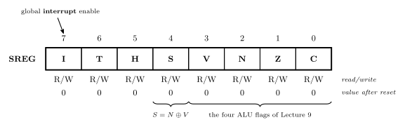
Figure 25: The status register, in the three-row form the datasheet uses: bit numbers above, flag names in the boxes, then the access row and the value each bit takes after reset. The callout names bit 7, the global interrupt enable; the braces underneath mark the four ALU flags and the sign flag \(S = N \oplus V\).
Instruction descriptions refer to these as SREG(n) by bit number:
| Flag | Bit | Meaning |
|---|---|---|
| C | SREG(0) | carry — was a carry out generated? |
| Z | SREG(1) | zero — was the result 0? |
| N | SREG(2) | negative — the sign bit of the result |
| V | SREG(3) | overflow — did a two’s complement addition/subtraction overflow? |
| S | SREG(4) | sign, \(= N \oplus V\) — the sign of the result corrected for any overflow |
| H | SREG(5) | half-carry — carry out of bit 3 |
| T | SREG(6) | transfer bit, used by BLD and BST |
| I | SREG(7) | global interrupt enable — set by sei, cleared by cli; cleared by the hardware when it takes an interrupt and set again by reti (avr-interrupts) |
C, Z, N and V are exactly the four flags of fetch-decode-execute-cycle.
S is not simply “the sign bit” — that is N. \(S = N \oplus V\) means: the result is negative (with no overflow), or would have been negative had overflow not occurred. That correction is what makes signed comparisons work, which is why the signed branches (BRLT, BRGE) test S while the unsigned ones (BRLO, BRSH) test C. The four cases — including the overflow case where N alone gives the wrong answer — are drawn in 2026-09-14-flow-of-control, and the branch pairs are tabulated in avr-branches-and-jumps.
The one-line meanings and the SREG(n) numbering are those of Atmel’s AVR Instruction Set Manual and the instruction summary in the ATmega324A datasheet. The I/O register map is the I/O register summary, pages 636–639 of the ATmega164A/324A/644A/1284P datasheet, which writes the I/O register number first and the data memory address in parentheses after it.
On-chip peripherals (ATmega324A)
Beyond the CPU and its memories, the chip carries a large set of peripherals — this is what makes it a microcontroller rather than a processor. The two figures nest: the whole of Figure 24 is what sits inside the single box marked AVR CPU in Figure 26.
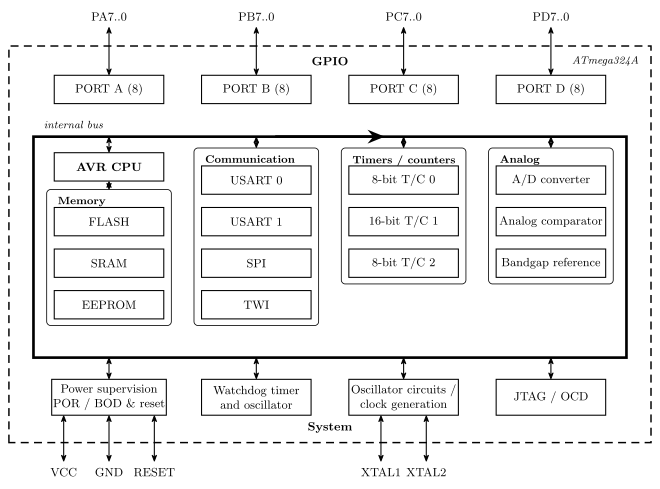
Figure 26: What is on the ATmega324A: the datasheet block diagram, rearranged into clusters by kind of thing — GPIO, memory, communication, timers/counters, analog and system. The dashed outline is the package boundary and the heavy rectangle inside it the internal bus, both as the datasheet draws them; the individual peripheral-to-port wiring is left out.
| Group | On the chip |
|---|---|
| General purpose I/O | PORT A, PORT B, PORT C, PORT D — four 8-bit ports |
| Communication | USART 0, USART 1, SPI, TWI |
| Timers/counters | 8-bit T/C 0, 16-bit T/C 1, 8-bit T/C 2 (T/C 3 is on the ATmega1284/1284P, not the 324A — the family datasheet’s block diagram covers both) |
| Analog | A/D converter, analog comparator, internal bandgap reference |
| Memory | Flash (program), SRAM (data), EEPROM (data, non-volatile) |
| System | Power supervision (POR/BOD & reset), watchdog timer and oscillator, oscillator/clock generation (XTAL1, XTAL2), JTAG/OCD |
There are three memories with three different jobs: flash for the program, SRAM for volatile working data, and EEPROM for data that must survive a power cycle. SRAM and EEPROM are the pair to keep straight: both hold data, and they differ only in surviving a power cycle.
See also
- cpu-organisation · fetch-decode-execute-cycle · instruction-set-architecture
- avr-instructions — the instruction set this hardware runs
- avr-io-ports — the I/O registers and the four GPIO ports
- avr-interrupts — the I bit, the vector table and the peripherals’ interrupt sources
- avr-timers-and-counters · avr-usart · avr-spi · analog-to-digital-conversion — four of the peripherals in detail
- memory-models · addressing-modes — the two address spaces, and how instructions name them
- assembly-process — flash, SRAM and EEPROM as the assembler’s three segments
- memory-technologies — flash, SRAM and EEPROM as technologies, and what the boot loader section is for · memory-hierarchy-and-cache — where the registers and SRAM sit by speed, and why the AVR needs no cache
- binary-number-representations — the flags’ two’s complement interpretation
- 2026-08-27-avr-introduction — Lecture 10
- 2026-08-31-instruction-set-architecture-part-1 — Lecture 11
AVR Branches and Jumps
How an AVR program’s control leaves the straight line: the ten conditional branches and which status flag each one reads, why greater than needs two different instructions for signed and unsigned bytes, the three unconditional jumps and how far each can reach, and the assembly idioms — if, if … else, counted and conditional loops — built from them. First met in 2026-09-14-flow-of-control, with the compare instructions and breq/brne first met in 2026-09-03-instruction-set-architecture-part-2. Procedure calls, the other way control moves, are in procedures-and-the-stack.
Flow of control
The flow of control is the sequence in which instructions actually execute. By default it is linear: every fetch-decode-execute cycle ends with \(PC \leftarrow PC + 1\) (fetch-decode-execute-cycle), so the next instruction is the next one in memory. Four kinds of instruction replace that increment with a new value:
| Decides | ||
|---|---|---|
| Branches | conditional | a status-register flag |
| Jumps | unconditional | nothing — always taken |
| Procedure calls and returns | unconditional, and they remember where they came from | procedures-and-the-stack |
| Interrupts / traps | triggered by hardware, not by an instruction | polling-and-interrupts · avr-interrupts |
Everything below is one instruction that writes the PC.
Conditional branches
A conditional branch tests one bit of the status register (avr-architecture) and, if the bit has the value the instruction wants, loads the PC with the address of a label; otherwise execution falls through to the next instruction. There is one instruction per flag per value:
| Branch if flag = | C | N | V | S = N ⊕ V | Z | T | H | I |
|---|---|---|---|---|---|---|---|---|
| 0 | brsh (= brcc) |
brpl |
brvc |
brge |
brne |
brtc |
brhc |
brid |
| 1 | brlo (= brcs) |
brmi |
brvs |
brlt |
breq |
brts |
brhs |
brie |
The first five columns are the ten branches counted above; the last three are the same pattern applied to the remaining flags and are in the instruction set reference. The mnemonics read as the condition, not the flag: brsh is branch if same or higher and happens to be branch if carry clear; brge is branch if greater or equal and happens to be branch if S clear. Learn them as conditions and the flags take care of themselves.
Every branch is relative and short. The offset is seven bits, so a conditional branch can reach only about 64 words either side of itself. For a farther target, branch on the opposite condition around a jmp:
    cp   r5, r6
    brne skip          ; opposite of the condition wanted
    jmp  far_away      ; taken only when r5 == r6
skip:
A taken branch costs two cycles, a not-taken one; the branch itself is one 16-bit word.
Setting the flags first
A branch reads flags; something has to have written them. Usually that is a compare (avr-instructions):
| Computes | Keeps | |
|---|---|---|
cp rd, rr |
rd − rr |
flags only |
cpi rd, K |
rd − K |
flags only — rd must be r16–r31 |
tst rd |
rd AND rd |
flags only — Z and N say whether rd is zero or negative |
but any ALU instruction sets flags, and a branch straight after an add, sub, dec or andi tests the result of that. dec r17 followed by brne loop is the standard loop counter, and no cp is needed. The rule from avr-program-structure holds either way: nothing that disturbs the flag may sit between the setter and the branch.
Signed and unsigned comparisons
Equality is the same question for signed and unsigned bytes, so breq and brne serve both. Ordering is not: whether 1111 1111 is bigger than 0000 0001 depends on whether it means 255 or −1, and the bits alone cannot say (binary-number-representations). The cp sets the same flags either way; the programmer chooses which pair of branches to read them with, and thereby declares the type:
Branch if rd ≥ rr |
Branch if rd < rr |
Reads | |
|---|---|---|---|
| unsigned | brsh — same or higher |
brlo — lower |
C: an unsigned subtraction needs a borrow exactly when the result went below zero |
| signed | brge — greater or equal |
brlt — less than |
S = N ⊕ V: the sign of the result, corrected for overflow |
Figure 27: The same two bit patterns on the two number lines an 8-bit register can be read against. As unsigned values, 0xFF is 255 and sits at the far right, above 0x01; as two’s complement values it is \(-1\) and sits just left of zero, below 0x01. One cp r5, r6 produces one set of flags for both readings. The unsigned branches take their answer from the carry flag, which records whether the subtraction had to borrow; the signed branches take theirs from S, which is the sign of the difference with any overflow undone. Choosing brsh or brlt after the compare is the only place the program says which line it meant.
Why S and not N. N is the top bit of the 8-bit result. When a signed subtraction overflows — a large positive minus a large negative, say — the true difference does not fit in 8 bits, the stored result wraps, and its top bit is the opposite of the true sign. V is set in exactly that case. So \(S = N \oplus V\) is the true sign whether or not overflow happened, and one flag test decides < correctly across the whole range; the four cases are drawn in 2026-09-14-flow-of-control. In C none of this is visible: the compiler reads the variable’s declared type and emits brlo for unsigned char and brlt for char, the same way it picks lsr or asr for >> (c-operators).
Unconditional jumps
| Instruction | Target | Size | Cycles | Reach |
|---|---|---|---|---|
jmp label |
absolute address | 32-bit (two words) | 3 | anywhere in program memory |
rjmp label |
PC + signed offset | 16-bit | 2 | ±2 K words (12-bit offset, −2048 to +2047) |
ijmp |
the address held in Z | 16-bit | 2 | anywhere; the target is a run-time value |
jmp carries a full program-memory address — 14 bits for the ATmega324A’s 16 K words of flash — which does not fit beside an opcode in one 16-bit word, so it takes two words and an extra cycle. rjmp carries a 12-bit offset from the instruction’s own position in one word, one cycle less, and reaches ±2 K words; in a program of a few hundred instructions every jump is within range, and it is the normal choice. ijmp takes the destination from Z, the pointer register of addressing-modes, so a program can compute where to go — a jump table, or C’s switch. The assembler resolves labels to addresses or offsets for all three; the programmer writes the label.
Figure 28: How far each kind of jump can reach from the instruction executing it. Program memory is the ATmega324A’s 16,K words; the marker is the current PC. A conditional branch carries a 7-bit offset and reaches about 64 words either way, an rjmp carries a 12-bit offset and reaches 2,K words either way, and a jmp carries the whole 14-bit address and reaches anywhere. The three are drawn to scale against the memory: the branch window is a sliver, the rjmp window covers a quarter of the chip, and the labs’ programs never leave either. The narrower the reach, the shorter and faster the instruction.
The idioms
Every C control structure (c-control-flow) compiles to a handful of these shapes. The branch is always on the opposite of the source condition, because what the branch does is skip the body.
if:
    cp   r5, r6
    brlt endif         ; skip the body when r5 < r6 (signed)
    ...                ; body: runs when r5 >= r6
endif:
if … else — the else part is the code the branch does not skip, and it needs a jmp past the if part:
    cp   r5, r6
    brge then
    ...                ; else part
    rjmp endif
then:
    ...                ; if part
endif:
while — test at the top, jump back at the bottom:
loop:
    cp   r5, r6
    brsh done          ; exit when r5 >= r6 (unsigned)
    ...                ; body
    rjmp loop
done:
Counted loop — count down to zero so the decrement sets Z for free:
    ldi  r17, 10       ; ten times
loop:
    ...                ; body
    dec  r17           ; sets Z when r17 reaches 0
    brne loop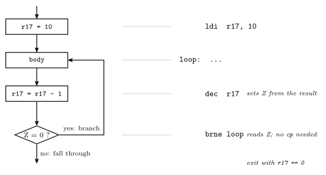
Figure 29: A counted loop, as a flowchart and as the four instructions that implement it. The counter is loaded once; the body runs; the decrement both updates the counter and sets the zero flag from the result; brne reads that flag and either returns to the label or falls out. Counting down rather than up saves the compare: dec leaves Z = 1 exactly when the counter has reached zero, so the branch tests the arithmetic directly. The body executes ten times, with r17 holding 10 down to 1 inside it and 0 on exit — the assembly form of for (i = 10; i != 0; i--).
Picking the branch. Write the C condition, decide signed or unsigned, and take the opposite instruction from the table:
| Source condition | Unsigned: skip with | Signed: skip with |
|---|---|---|
a == b |
brne |
brne |
a != b |
breq |
breq |
a < b |
brsh |
brge |
a >= b |
brlo |
brlt |
a > b |
swap operands: cp b, a then brsh |
cp b, a then brge |
a <= b |
cp b, a then brlo |
cp b, a then brlt |
There is no greater than branch; a > b is b < a, so compare the other way round.
See also
- avr-program-structure — labels, the template, and compare-then-branch drawn out
- procedures-and-the-stack —
call,rcall,icallandret: the jumps that come back - polling-and-interrupts — the fourth way the PC leaves its sequence, with no instruction asking
- avr-instructions —
cp,cpi,tst,dec, and which flags each instruction sets - avr-architecture — the status register; \(S = N \oplus V\)
- c-control-flow — the same shapes in C · binary-number-representations — signed and unsigned bytes
- assembly-process — how the assembler gives a label its address, counting each
jmpas two words - 2026-09-14-flow-of-control — Lecture 15 · 2026-09-03-instruction-set-architecture-part-2 — Lecture 12
AVR Instructions
The AVR instructions introduced so far, in assembly and in machine code. See instruction-set-architecture for what an instruction set is and avr-architecture for the hardware that runs these.
The full alphabetical instruction set — each mnemonic with its operation, description, flags affected, clock count, opcode pattern and an example — is in the AVR instruction set reference: Atmel’s AVR Instruction Set Manual, and the instruction summary in the ATmega324A datasheet the course says to keep open. The notation key immediately below and the per-instruction flag table at the end are unverified against that reference — check them against your own copy before leaning on them.
Reading the instruction set reference
Operand notation — how an operand’s allowed values map onto opcode bits:
| Notation | Meaning | Values | Opcode pattern |
|---|---|---|---|
Rd |
destination register (may be a source too) | r0…r31 | ddddd |
| r16…r31 | dddd (register number − 16) |
||
Rr |
source register | r0…r31 | rrrrr |
Rh:Rl |
register pair as a 16-bit quantity | r25:r24 / X / Y / Z | dd (00 / 01 / 10 / 11) |
K |
constant data | 0…255 | KKKKKKKK |
k |
constant address | −64…63, −2048…2047, 0…65535 | kkkkkkk … kkkk kkkk kkkk kkkk |
b |
bit number in a register | 0…7 | bbb |
s |
bit in the status register | 0…7 | sss |
P |
I/O register number | 0…63 | PPPPPP |
q |
displacement for direct addressing | 0…63 | qqqqqq |
The Rd row is the whole story behind LDI’s restriction — an instruction spending five bits on the register gets all 32; one spending four gets sixteen, and pays for it by starting at r16.
Operation notation — used in the Operation column:
M[a] / PM[a] / IO[a] |
SRAM cell / program memory (flash) byte / I/O register at address a |
PC / SP / STACK |
program counter / stack pointer / M[SP] |
← |
assigned value |
reg(a) |
bit a of register reg, numbered 7…0 most to least significant |
Flag names in the Flags Affected column are the SREG bits of avr-architecture.
Register conventions
Two operand names recur throughout the instruction set:
rd— the destination register.rr— the source register.
AVR is a two-operand machine: the destination is also one of the sources, so add rd, rr means rd ← rd + rr. (Contrast a three-operand ISA such as ARM, where add rd, r1, r2 leaves both sources untouched.) This matters when reading code — an AVR arithmetic instruction always overwrites one of its inputs.
Instructions by type
The instruction set can be cut two ways.
By what the instruction touches — the instruction-type list of instruction-set-architecture, filled in with the instructions so far:
| Type | Does | AVR so far |
|---|---|---|
| Input/Output | communicate with I/O devices/ports | IN, OUT |
| Load/Store | move data from/to memory | LD, LDS, ST, STS |
| Move | copy data between registers | MOV |
| Arithmetic | addition, subtraction, … | ADD, ADC, SUB, INC, NEG |
| Logical | Boolean operations | AND, ANDI, OR, ORI, EOR, COM |
| Branching | deciding which instruction to perform next | JMP, BREQ, BRNE |
By operand count, which splits the arithmetic and logical group instead:
| AVR examples | ||
|---|---|---|
| Dyadic | combine 2 operands to produce a result | add r5, r6 (arithmetic) · and r5, r6 (logical, bitwise) |
| Monadic | one operand → one result | ser r16 (set) · clr r5 (clear) · neg r5 (2’s complement) · com r5 (1’s complement) · the shifts and rotates |
The second cut is the one that predicts the syntax: a dyadic instruction has a comma in it, a monadic one does not.
The instructions so far
| Instruction | Meaning | Example |
|---|---|---|
MOV rd, rr |
copy contents of rr into rd — rd ← rr |
mov r3, r14 |
ADD rd, rr |
add contents of rr to rd — rd ← rd + rr |
add r5, r6 |
ADC rd, rr |
add with carry — rd ← rd + rr + C |
adc r11, r5 |
AND rd, rr |
bitwise AND, result into rd |
|
OR rd, rr |
bitwise OR, result into rd |
|
EOR rd, rr |
bitwise exclusive-OR, result into rd |
|
INC rd |
rd ← rd + 1 |
inc r22 |
LDI rd, number |
load immediate — put the number into rd |
ldi r16, 73 |
SER rd |
set all bits — rd ← $FF. Same as ldi rd, 0xFF, so r16–r31 only |
ser r17 |
CLR rd |
clear all bits — rd ← 0. Same as eor rd, rd, so any register |
clr r3 |
SUB rd, rr |
rd ← rd − rr |
sub r7, r19 |
COM rd |
one’s complement — flip all bits | com r8 |
NEG rd |
two’s complement — negate | neg r9 |
ANDI rd, K |
bitwise AND with a constant — r16–r31 only | andi r16, 0x01 |
ORI rd, K |
bitwise OR with a constant — r16–r31 only | ori r16, 0xF0 |
MOV is named misleadingly: it copies, it does not move. The source register is unchanged. It also affects no flags, which is what makes it safe to shuffle values between operations without disturbing the status register.
SER and CLR are short-hand ways of setting/clearing all bits of a register, and their restrictions differ because their expansions do:
| Exactly the same as | Reaches | |
|---|---|---|
ser rd (set register) |
ldi rd, 0xFF |
r16–r31 only — it inherits LDI’s four-bit register field |
clr rd (clear register) |
eor rd, rd |
any register, r0–r31 — EOR is a two-register instruction with five bits for each |
So clr r3 is legal and ser r3 is not, which looks arbitrary until you look at what each one assembles to. clr is also the reason \(X \oplus X = 0\) from bit-masking is worth remembering: XORing a register with itself is how the machine zeroes one.
Compare instructions
These do the arithmetic, discard the result, and keep only the flags — which is exactly what a conditional branch needs.
| Instruction | Does | Note |
|---|---|---|
CP rd, rr |
rd − rr |
compares two registers |
CPI rd, K |
rd − K |
compares against a constant — like ldi, r16–r31 only |
TST rd |
rd AND rd |
examines one register; literally the same operation as and rd, rd |
tst looks odd until you notice that ANDing a value with itself leaves it unchanged (\(X \cdot X = X\)) but still sets N and Z from it — so it is a zero/sign test that costs nothing and clobbers nothing. See bit-masking.
A comparison is the same as subtraction, with the result not saved — it exists only to set status register flags (Z, N, C, V …). And the instruction reference specifies which status register bits are set by which instructions: the flags are defined per instruction rather than falling out of one shared adder, which is the point of the table at the end of this note.
Branch instructions
Based on status register values — the flags a compare just set:
Branches to label if |
|
|---|---|
BREQ label |
Z = 1 |
BRNE label |
Z = 0 |
Together with CP that is a complete conditional: compare, which sets Z exactly when the two operands were equal, then branch on Z.
    cp   r5, r6          ; r5 - r6, result thrown away, flags kept
    breq same            ; Z = 1, i.e. r5 == r6
JMP label is the unconditional version — it tests nothing and always goes. Labels, and the program skeleton the branches live in, are in avr-program-structure.
breq/brne are two of ten: there is one branch per status flag per value, and the pairs that matter for ordering are brsh/brlo (unsigned, on C) and brge/brlt (signed, on S) — the full table, and why the signed pair reads S rather than N, are in avr-branches-and-jumps.
Control flow
The instructions that write the PC, and the two stack instructions that go with the calls (avr-branches-and-jumps, procedures-and-the-stack):
| Instruction | Does | Words | Cycles |
|---|---|---|---|
BRxx label |
branch if a flag has the wanted value; reach ±64 words | 1 | 1 (not taken) / 2 (taken) |
JMP label |
PC ← address of label |
2 | 3 |
RJMP label |
PC ← PC + offset; reach ±2 K words | 1 | 2 |
IJMP |
PC ← Z | 1 | 2 |
CALL label |
push the return address, then as JMP |
2 | 4 |
RCALL label |
push the return address, then as RJMP |
1 | 3 |
ICALL |
push the return address, then as IJMP |
1 | 3 |
RET |
pop the return address into PC | 1 | 4 |
PUSH rr |
store rr at SP, SP ← SP − 1 |
1 | 2 |
POP rd |
SP ← SP + 1, load rd from SP |
1 | 2 |
None of these touches the status register except by what the pushed and popped values happen to be; a call between a cp and its branch is safe only if the procedure preserves the flags, which in practice means it is not.
Three more belong to interrupts, and between them they are the only instructions that change the I bit (avr-interrupts):
| Instruction | Does | Words | Cycles |
|---|---|---|---|
SEI |
I ← 1: interrupts enabled | 1 | 1 |
CLI |
I ← 0: interrupts disabled | 1 | 1 |
RETI |
pop the return address into PC, and I ← 1 | 1 | 4 |
RETI is RET plus set I. A handler that ends in RET returns to the right place and leaves interrupts off for good.
Data movement
Data is usually copied, not moved — in every instruction below the source is left alone. What changes is where the two ends are:
| Direction | Called | AVR |
|---|---|---|
| register → register | move | mov |
| memory → register | load | lds, ld |
| register → memory | store | sts, st |
| I/O register → register | input | in |
| register → I/O register | output | out |
Three different places a value can live — a general purpose register, data memory, an I/O register — and a different instruction family for each. The one thing that is genuinely out of reach is SRAM from in/out: P only goes up to 0x3F, so those two never leave the first 64 I/O registers.
Everything else is a question of cost and numbering, not reachability. Because the I/O registers are mapped into the data space (avr-io-ports), lds/sts can reach one — in r16, 0x09 and lds r16, 0x29 both read PIND, the second for two instruction words instead of one. The bug to actually watch for is writing the I/O register number where the data address belongs, or the reverse.
Load and store
| Does | Addressing | Words | Cycles | |
|---|---|---|---|---|
LD rd, X |
rd ← Mem[X] |
indirect — address in the pointer register | 1 | 2 |
ST X, rr |
Mem[X] ← rr |
indirect | 1 | 2 |
LDS rd, k |
rd ← Mem[k] |
direct — 16-bit address in the instruction | 2 (32 bits) | 2 |
STS k, rr |
Mem[k] ← rr |
direct | 2 | 2 |
For example:
    ld   r5, X           ; r5 <- Mem[X]
    st   X, r5           ; Mem[X] <- r5
    lds  r5, 0x20        ; r5 <- Mem[0x20]
    sts  0x20, r5        ; Mem[0x20] <- r5
Both pairs reach the same data space — the difference is only where the address comes from (addressing-modes), and lds/sts pay a second instruction word for spelling it out. X here is the pointer pair of avr-architecture.
In and out
| Does | Words | Cycles | |
|---|---|---|---|
IN rd, P |
rd ← I/O register P |
1 | 1 |
OUT P, rr |
I/O register P ← rr |
1 | 1 |
rd/rr may be any of r0–r31 — unlike ldi, these are not restricted to the top half — and P is an I/O register number 0–63 (0x00–0x3F) or a name from m324Adef.inc. Examples: in r5, 0x26 (I/O register 0x26 is TCNT0) and out PORTD, r6. Full treatment in avr-io-ports.
One word and one cycle makes these the cheapest access on the chip — cheaper than reaching the very same register through lds/sts, which is the whole reason the first 64 I/O registers are special.
Shifts and rotates
Monadic instructions that move every bit one place. They differ only in what arrives at the vacated end and what happens to the bit that falls off — and in all five, the bit that falls off lands in C.
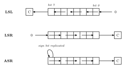
Figure 30: The three shift instructions. LSL and LSR feed a 0 into the vacated end; ASR feeds the sign bit back into itself, which is what makes it a signed division. In all three the bit shifted out lands in the carry flag.
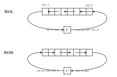
Figure 31: The two rotate instructions. A rotate is a shift whose vacated end is fed from the carry flag instead of a constant, so the register and C together behave as a nine-bit ring.
| Name | Into the vacated end | Out | |
|---|---|---|---|
LSL rd |
Logical Shift Left | 0 → bit 0 |
bit 7 → C |
LSR rd |
Logical Shift Right | 0 → bit 7 |
bit 0 → C |
ASR rd |
Arithmetic Shift Right | bit 7 replicated into itself | bit 0 → C |
ROL rd |
ROtate Left through carry | C → bit 0 | bit 7 → C |
ROR rd |
ROtate Right through carry | C → bit 7 | bit 0 → C |
What they compute
Shifting a binary number one place is multiplying or dividing it by two, which is the whole reason these exist. Using four bits for legibility:
| Worked example | ||
|---|---|---|
LSL |
× 2 | 0010 (2) → 0100 (4) → 1000 (8) |
LSR |
÷ 2, read unsigned | 0110 (6) → 0011 (3); 1000 (8 unsigned) → 0100 (4) |
ASR |
÷ 2, read signed | 1000 (\(-8\)) → 1100 (\(-4\)) |
LSR and ASR are the pair to keep straight. Given 1000, LSR produces 0100 — right if the value meant unsigned 8, wrong if it meant \(-8\). ASR replicates the sign bit into the vacated position and produces 1100 \(= -4\). The same bits go in; the instruction is where you declare which interpretation you meant (binary-number-representations).
There is no matching pair going the other way, because left shifts need no such distinction: a 0 always enters at the bottom, and the signed and unsigned readings of “× 2” agree — right up until the result stops fitting in eight bits.
Shifting a value wider than eight bits
Rotates exist to carry a bit from one byte into the next. To multiply the 16-bit unsigned value in r13:r14 by two (so r13 is the high byte, r14 the low):
    lsl  r14             ; low byte x2; bit 7 falls out into C
    rol  r13             ; high byte x2, pulling C into its bit 0
LSL on the low byte pushes its top bit into C; ROL on the high byte pulls exactly that bit back in at the bottom. The two instructions together shift a sixteen-bit quantity one place.
The wrong answers are worth naming, because each fails differently. lsl r13 (and asl r13, which is the same operation under another name — shifting left, a 0 always enters) shifts the high byte but feeds it a 0, discarding the bit the low byte just produced. rol r14 rotates the wrong byte.
Building wider operations from 8-bit ones
The AVR supports exactly one data type in hardware — an 8-bit integer (instruction-set-architecture). Everything wider is a sequence of instructions, and C is what stitches the pieces together.
Add the 16-bit quantity r5:r4 to r11:r10, result in r11:r10 — high byte named first, so r4 and r10 are the low bytes:
    add  r10, r4         ; r10 <- r10 + r4        (low bytes; carry out lands in C)
    adc  r11, r5         ; r11 <- r11 + r5 + C    (high bytes, plus that carry)
ADD on the low bytes leaves any carry out of bit 7 in C, and ADC on the high bytes adds it back in — the same column-by-column carrying as long addition on paper, one byte per column.
The order is not negotiable, and neither is what sits between the two lines: adc has to run after the add that produced the carry, and any instruction in between that touches C ruins the result. That is the general shape of multi-byte arithmetic on an 8-bit machine — low end first, and nothing allowed to disturb the flag in the middle.
Constants
Constants do not have to be hexadecimal. All five of these load the same value into r17:
| Written | Radix | |
|---|---|---|
ldi r17, 0x34 |
hexadecimal | 0x prefix |
ldi r17, $34 |
hexadecimal | $ prefix |
ldi r17, 52 |
decimal | no prefix |
ldi r17, 064 |
octal | a leading 0 |
ldi r17, 0b00110100 |
binary | 0b prefix |
\(\texttt{0x34} = 52 = 64_8 = \texttt{0b00110100}\). The octal form is the trap: a leading zero changes the radix, so 012 is 10, not 12.
LDI’s restrictions
LDI is the one with strings attached:
- Registers r16 to r31 only. Not r0–r15.
- 8-bit numbers,
00000000to11111111. Written in decimal the range is \(-128\) to \(255\) — that span covers both the signed and the unsigned reading of eight bits.
A counter-example, and the legal version of it:
    ldi  r0, 5           ; NOT legal - r0 is below r16
    ldi  r16, 5          ; the same idea, in a register ldi can reach
The register restriction is not arbitrary: it falls straight out of the encoding below, which has only four bits for the register number.
Machine code
Each instruction is a 16-bit word made of an opcode and operand bit fields — see instruction-set-architecture. In the AVR datasheet’s notation, a format like 0000 11rd dddd rrrr means the literal bits are fixed and each letter is one bit of an operand, gathered from wherever it appears.
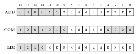
Figure 32: Three AVR instruction encodings, each 16 bits. Fixed opcode bits are shaded; letters are operand bits. In ADD and LDI the operand bits are not contiguous — the register number’s top bit sits apart from the rest, and LDI’s constant is split into two nibbles either side of the register field.
ADD — 0000 11rd dddd rrrr
The opcode is bits 15–10, 0000 11 — six fixed bits, all that is left once the two five-bit register numbers have taken ten of the sixteen. The destination register number is d dddd — five bits, so all 32 registers — and the source is r rrrr. Both have their top bit separated from the other four, and note the order in the middle nibble: the source’s top bit (r, bit 9) comes before the destination’s (d, bit 8), even though the mnemonic writes the destination first.
Worked example: add r23, r7.
| Register | In binary (5 bits) | Split as | |
|---|---|---|---|
rd |
r23 = 16 + 4 + 2 + 1 | 10111 |
d = 1, dddd = 0111 |
rr |
r7 = 4 + 2 + 1 | 00111 |
r = 0, rrrr = 0111 |
Dropping those into 0000 11rd dddd rrrr:
\[\texttt{0000 1101 0111 0111}\]
Figure 33: Assembling add r23, r7. Each register number is written as five bits, then torn in two: the top bit goes into the middle nibble and the low four into their own field. Shading, not position, is what tells the two operands apart here. The two guide lines cross because the destination’s bit sits between the source’s two pieces.
COM — 1001 010d dddd 0000
Flip all bits — one’s complement. One register operand, again as d dddd.
Worked example: com r19. r19 = 16 + 2 + 1 = 10011, so d = 1 and dddd = 0011:
\[\texttt{1001 0101 0011 0000}\]
LDI — 1110 KKKK dddd KKKK
Two operand fields:
K— the 8-bit constant, split into two nibbles: the high four bits in the firstKKKKfield, the low four in the last.d— the register number minus 16.
That subtraction is why LDI only reaches r16–r31: the field is four bits, so it can express \(2^4 = 16\) distinct registers, and the ISA spends them on the top half of the register file.
Applying the rule to ldi r16, 73: \(d = 16 - 16 = 0\), so dddd = 0000; \(73 = \texttt{0100 1001}\), so the high nibble is 0100 and the low nibble 1001:
\[\texttt{1110 0100 0000 1001}\]
Flags, by instruction
The reference’s Flags Affected column is worth reading rather than assuming — the flags are defined per instruction, not derived from a single adder. For the instructions above:
| Instruction | Z | C | N | V |
|---|---|---|---|---|
MOV, LDI, SER |
— | — | — | — |
AND, ANDI, OR, ORI, EOR, TST |
from result | unchanged | from result | cleared to 0 |
ADD, ADC, SUB, CP, CPI |
from result | from carry/borrow | from result | signed overflow |
CLR |
always 1 | unchanged | always 0 | cleared to 0 |
COM |
from result | always set to 1 | from result | cleared to 0 |
NEG |
from result | set unless the result is $00 |
from result | set only if the result is $80 |
Two of these will catch you out. The logical operations leave C alone entirely — whatever it held before an and it still holds after. And COM sets C unconditionally, which is not a carry out of anything; it is a defined convention, chosen so that com followed by an increment behaves like a negation.
The CLR row is just the logical row with a result that is guaranteed to be 0x00 — clr rd is eor rd, rd — which makes it the one instruction whose flags you can predict without knowing the operand.
For the shift, rotate and branch instructions, look the flags up in the reference rather than guessing. The one part that is visible in the diagrams above is C: every shift and rotate sets it from the bit that fell out. The rest is defined per instruction, as the paragraph opening this section warns.
For ADD specifically, the manual gives the flags as Boolean formulas over the operand and result bits, writing \(R\) for the result (which equals Rd after the operation):
\[N = R_7 \qquad Z = \overline{R_7}\cdot\overline{R_6}\cdot\overline{R_5}\cdot\overline{R_4}\cdot\overline{R_3}\cdot\overline{R_2}\cdot\overline{R_1}\cdot\overline{R_0}\] \[V = Rd_7 \cdot Rr_7 \cdot \overline{R_7} + \overline{Rd_7}\cdot\overline{Rr_7}\cdot R_7 \qquad C = Rd_7 \cdot Rr_7 + Rr_7 \cdot \overline{R_7} + \overline{R_7}\cdot Rd_7\]
\(Z\) is a NOR over every result bit. \(V\) says overflow happened exactly when both operands had the same sign and the result’s differs — two negatives giving a positive, or two positives giving a negative. And \(S = N \oplus V\), for signed tests. See avr-architecture.
See also
- instruction-set-architecture · avr-architecture · bit-masking
- avr-io-ports — the I/O registers
in/outreach - addressing-modes — the four ways an operand names its value
- avr-program-structure — labels,
jmpand the program skeleton - avr-interrupts —
sei,cli,reti, and which flags an interrupt handler must save - binary-number-representations — one’s and two’s complement, and the \(-128\) to \(255\) range
- 2026-08-27-avr-introduction — Lecture 10
- 2026-09-03-instruction-set-architecture-part-2 — Lecture 12
AVR Interrupts
How the ATmega324A implements interrupts, and how to write one and switch it on, in assembly and in C: the path from a device’s request to the handler and back, the vector table, the switches that decide whether a request is taken, the ISR template and its stack, ISR() and the _vect names, volatile, priority, and a complete timer-interrupt program. First met in 2026-09-21-interrupts. What an interrupt is on any CPU (polling versus interrupts, the fourteen-step sequence, transparency, nesting) is polling-and-interrupts.
The path of an interrupt
An interrupt is a procedure call the hardware makes (procedures-and-the-stack). The CPU finishes the instruction in progress, pushes the address of the next one, turns interrupts off and loads the PC with the address of the vector table entry for the source. The entry holds a jmp to the handler. The handler ends with reti, which pops the return address and turns interrupts back on.
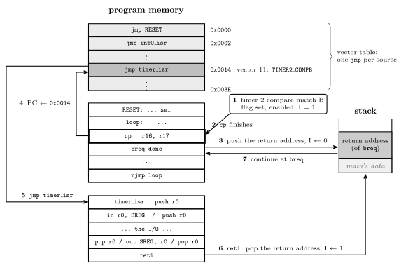
Figure 34: One timer interrupt from start to finish. The request (1) arrives while cp is executing, and the CPU lets it finish (2): an AVR instruction is never abandoned halfway. The hardware then pushes the address of the next instruction, breq, clears the I bit (3), and loads the PC with 0x0014 (4), the vector table entry for Timer/Counter 2 compare match B. The jmp stored there reaches the handler (5), which saves what it uses, does its work, restores, and ends with reti (6). That pops the return address and sets I again, and execution continues at breq (7) as if nothing had happened. It will, provided the handler restored the status register, because breq is about to read the Z flag that cp set. Nothing in the main program refers to the handler; the vector table is the only link between them.
The vector table
The first addresses of program memory hold the interrupt vector table: one entry per interrupt source, in a fixed order, each a two-word jmp to that source’s handler (avr-branches-and-jumps). The AVR uses a table of jump instructions, not a table of addresses. When it takes an interrupt it loads the PC with the address of the entry itself and executes what it finds there. So:
\[\text{entry address} = 2 \times (\text{vector} - 1)\]
RESET is vector 1, at 0x0000. A reset is taken through the same table as an interrupt, which is why every program begins with jmp RESET (avr-program-structure). The table has 31 entries on the ATmega324A and ends at 0x003C, so the program proper starts at 0x003E.
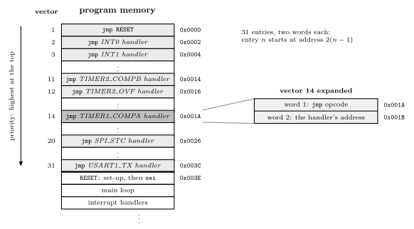
Figure 35: The bottom of program memory. Each vector-table entry is two words, the two halves of a jmp, so entry \(n\) sits at address \(2(n-1)\), and the table’s order is also its priority order: when two requests are waiting, the one nearer the top is taken first. The expanded entry shows what one of them holds, taking vector 14, Timer/Counter 1 compare match A, as the example. An entry for a source the program does not use can hold anything, as long as that interrupt is never enabled. The program itself starts at the first address after the table, which the jmp in entry 1 reaches at reset.
The full table for the ATmega324A, from pages 69–70 of the datasheet. The Group column sorts the sources by kind: GPIO, T/C, Comms, analog and system. The C name is the Source followed by _vect.
| Vector | Address | Source | Interrupt definition | Group | C handler |
|---|---|---|---|---|---|
| 1 | 0x0000 |
RESET |
RESET, watchdog reset, etc. | — | — (the program’s start) |
| 2 | 0x0002 |
INT0 |
External Interrupt Request 0 | GPIO | ISR(INT0_vect) |
| 3 | 0x0004 |
INT1 |
External Interrupt Request 1 | GPIO | ISR(INT1_vect) |
| 4 | 0x0006 |
INT2 |
External Interrupt Request 2 | GPIO | ISR(INT2_vect) |
| 5 | 0x0008 |
PCINT0 |
Pin Change Interrupt Request 0 (port A) | GPIO | ISR(PCINT0_vect) |
| 6 | 0x000A |
PCINT1 |
Pin Change Interrupt Request 1 (port B) | GPIO | ISR(PCINT1_vect) |
| 7 | 0x000C |
PCINT2 |
Pin Change Interrupt Request 2 (port C) | GPIO | ISR(PCINT2_vect) |
| 8 | 0x000E |
PCINT3 |
Pin Change Interrupt Request 3 (port D) | GPIO | ISR(PCINT3_vect) |
| 9 | 0x0010 |
WDT |
Watchdog Time-out Interrupt | system | ISR(WDT_vect) |
| 10 | 0x0012 |
TIMER2_COMPA |
Timer/Counter2 Compare Match A | T/C | ISR(TIMER2_COMPA_vect) |
| 11 | 0x0014 |
TIMER2_COMPB |
Timer/Counter2 Compare Match B | T/C | ISR(TIMER2_COMPB_vect) |
| 12 | 0x0016 |
TIMER2_OVF |
Timer/Counter2 Overflow | T/C | ISR(TIMER2_OVF_vect) |
| 13 | 0x0018 |
TIMER1_CAPT |
Timer/Counter1 Capture Event | T/C | ISR(TIMER1_CAPT_vect) |
| 14 | 0x001A |
TIMER1_COMPA |
Timer/Counter1 Compare Match A | T/C | ISR(TIMER1_COMPA_vect) |
| 15 | 0x001C |
TIMER1_COMPB |
Timer/Counter1 Compare Match B | T/C | ISR(TIMER1_COMPB_vect) |
| 16 | 0x001E |
TIMER1_OVF |
Timer/Counter1 Overflow | T/C | ISR(TIMER1_OVF_vect) |
| 17 | 0x0020 |
TIMER0_COMPA |
Timer/Counter0 Compare Match A | T/C | ISR(TIMER0_COMPA_vect) |
| 18 | 0x0022 |
TIMER0_COMPB |
Timer/Counter0 Compare Match B | T/C | ISR(TIMER0_COMPB_vect) |
| 19 | 0x0024 |
TIMER0_OVF |
Timer/Counter0 Overflow | T/C | ISR(TIMER0_OVF_vect) |
| 20 | 0x0026 |
SPI_STC |
SPI Serial Transfer Complete | Comms | ISR(SPI_STC_vect) |
| 21 | 0x0028 |
USART0_RX |
USART0 Receive Complete | Comms | ISR(USART0_RX_vect) |
| 22 | 0x002A |
USART0_UDRE |
USART0 Data Register Empty | Comms | ISR(USART0_UDRE_vect) |
| 23 | 0x002C |
USART0_TX |
USART0 Transmit Complete | Comms | ISR(USART0_TX_vect) |
| 24 | 0x002E |
ANALOG_COMP |
Analog Comparator | analog | ISR(ANALOG_COMP_vect) |
| 25 | 0x0030 |
ADC |
ADC Conversion Complete | analog | ISR(ADC_vect) |
| 26 | 0x0032 |
EE_READY |
EEPROM Ready | system | ISR(EE_READY_vect) |
| 27 | 0x0034 |
TWI |
2-wire Serial Interface | Comms | ISR(TWI_vect) |
| 28 | 0x0036 |
SPM_READY |
Store Program Memory Ready | system | ISR(SPM_READY_vect) |
| 29 | 0x0038 |
USART1_RX |
USART1 Receive Complete | Comms | ISR(USART1_RX_vect) |
| 30 | 0x003A |
USART1_UDRE |
USART1 Data Register Empty | Comms | ISR(USART1_UDRE_vect) |
| 31 | 0x003C |
USART1_TX |
USART1 Transmit Complete | Comms | ISR(USART1_TX_vect) |
Every timer event the course uses has its own vector. The three units’ compare matches and overflows are vectors 10–19, and a unit’s compare A and compare B are separate sources with separate handlers, just as they have separate flags (avr-timers-and-counters).
When a request is taken
Four things have to be true before a source’s handler runs. The four setup steps (set up the conditions, enable the interrupt, clear its flag, enable globally) arrange for them:
- The conditions for the interrupt are set up, so that the event can happen at all: a timer running in the right mode, or a pin configured to sense an edge.
- That particular interrupt is enabled, by its own bit in an I/O register. There is one bit per source.
- Its flag is set. The hardware does this when the event occurs, whether or not the interrupt is enabled. That is why the third setup step clears the flag before the interrupt is enabled: afterwards only a fresh event can set it, and an event from before the setup does not fire at once. Clearing is done by writing a 1 to the flag’s bit.
- Interrupts are enabled globally: the I bit of the status register is 1.
sei(orsei()in C) sets it.
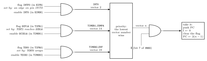
Figure 36: Whether a request becomes an interrupt, drawn as the logic it amounts to. Each source has a flag, set by its event, and an enable bit, set by the program. The source requests an interrupt only while both are 1, and all three sources here are gated the same way. If more than one is requesting, the lowest vector number wins. The winner is taken only if the I bit is also 1, and taking it clears I. For these sources, taking the vector also clears the flag. So a flag with its enable bit off simply stays set, available to be polled, and a flag that goes up while I is 0 waits and is taken the moment I returns to 1.
For the sources the course meets, the bits are:
| Source | Flag (register) | Enable (register) | Conditions set up in |
|---|---|---|---|
INT0 (pin PD2) |
INTF0 (EIFR) |
INT0 (EIMSK) |
EICRA: bits ISC01, ISC00 choose low level 00, any change 01, falling edge 10 or rising edge 11 |
TIMER0_COMPA |
OCF0A (TIFR0) |
OCIE0A (TIMSK0) |
TCCR0A, TCCR0B, OCR0A |
TIMER0_OVF |
TOV0 (TIFR0) |
TOIE0 (TIMSK0) |
TCCR0A, TCCR0B |
TIMER1_COMPA |
OCF1A (TIFR1) |
OCIE1A (TIMSK1) |
TCCR1A, TCCR1B, OCR1A |
TIMER1_OVF |
TOV1 (TIFR1) |
TOIE1 (TIMSK1) |
TCCR1A, TCCR1B |
The naming pattern is regular: an F for the flag and an IE for interrupt enable, with OC for output compare and TOV/TOIE for timer overflow. Each of these flags is cleared automatically when its vector is taken, so a handler does not normally clear its own flag. A program that polls a flag instead, with the interrupt left disabled, must clear it itself (avr-timers-and-counters).
The I bit
| I | Also | |
|---|---|---|
sei |
← 1 | |
cli |
← 0 | |
| taking an interrupt (hardware) | ← 0 | pushes PC, loads the vector address |
reti |
← 1 | pops PC |
I is bit 7 of SREG (avr-architecture), and it is 0 after reset, so no interrupt happens until the program executes sei. Because the hardware clears it on entry, a handler runs with interrupts off unless it turns them back on itself.
External interrupts
An external interrupt is requested by a pin. The ATmega324A has three, each fixed to one pin:
| Interrupt | Pin |
|---|---|
INT0 |
PD2 |
INT1 |
PD3 |
INT2 |
PB2 |
What the pin has to do to make a request is chosen by two sense control bits per interrupt, in EICRA:
ISCn1:0 |
A request is made |
|---|---|
00 |
for as long as the pin is low |
01 |
on any change of the pin |
10 |
on a falling edge, 1 to 0 |
11 |
on a rising edge, 0 to 1 |
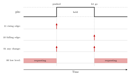
Figure 37: What each sense control setting responds to, for a push button that reads 1 while it is held. A rising edge is the moment the button is pushed and a falling edge is the moment it is let go. Any change gives a request at both. The low level setting is different in kind: it asks for the whole time the pin is low, so the handler runs again and again until the pin goes high.
Setting one up follows the same steps as any other interrupt. For a rising edge on INT0 and a falling edge on INT1:
ISR(INT0_vect) { /* PD2 went from 0 to 1 */ }
ISR(INT1_vect) { /* PD3 went from 1 to 0 */ }

/* in main */
EICRA = (1<<ISC01) | (1<<ISC00) | (1<<ISC11);   /* INT0 rising, INT1 falling */
EIMSK = (1<<INT0) | (1<<INT1);                  /* enable both               */
EIFR  = (1<<INTF0) | (1<<INTF1);                /* clear both flags          */
sei();- Edges fit buttons. An edge happens once per push, however long the button is held. That makes an external interrupt a natural way to act on a push or on a release without the program having to remember what the button was doing last time.
- Bounce. A mechanical contact chatters for a moment as it closes, and each chatter is an edge. One push can then run the handler several times.
- The low level setting keeps asking. If the pin is still low when the handler returns, the interrupt is taken again straight away.
- Priority.
INT0,INT1andINT2are vectors 2, 3 and 4, directly after reset, so they come before every timer and serial interrupt.
Used for the start/stop and reset buttons of a stopwatch in week9-lab-avr-interrupts.
Writing an ISR in assembly
The template:
isr_label:
    push r0              ; save r0: it is about to carry SREG
    in   r0, SREG
    push r0              ; save the interrupted program's flags

    ; ... perform the operation, usually input/output ...
    ; (any other register used: push it here, pop it below)

    pop  r0
    out  SREG, r0        ; flags back as they were
    pop  r0              ; r0 back as it was
    reti                 ; pop PC and set I
SREG cannot be pushed directly, because push takes a general-purpose register. So one register carries it, and that register is saved first. The restore is the save in reverse. Two consequences follow from where the save happens:
- The flags saved are the interrupted program’s. Apart from I, the hardware does not touch them on entry, and
pushchanges none, so the copy is exactly what the interrupted code left. - The saved I bit is 0, because the hardware cleared it before the first instruction of the ISR. Writing the copy back therefore leaves interrupts off until
reti, which is the right moment for them to come back.
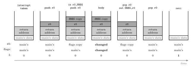
Figure 38: The stack through the ISR template, with the three things the interrupted program relies on (r0, its flags, and the I bit) traced underneath. The hardware’s push of the return address comes first, then the template’s two pushes, the SREG copy on top. The body is free to change r0 and the flags because both are safely on the stack. The restore pops the copy into r0 and writes it to SREG, then pops r0’s own value. When reti runs, the return address is on top again, exactly as the hardware left it. I stays 0 from entry to reti, the copy in the middle included, and it is reti that sets it.
Which registers to save is decided by what the body does. Save any register the body writes. Save SREG if any instruction in the body changes a flag, which rules in arithmetic, logic, compares and shifts but not in, out, ldi, mov, push or pop (avr-instructions). A handler that only copies a port to another port needs one register and no SREG at all (worked in 2026-09-21-interrupts).
Placing the entry in the table
The template in avr-program-structure puts jmp RESET at 0x0000 and leaves a comment where the handlers go. Once a vector is used, its jmp has to sit at exactly that vector’s address. The assembler’s .org directive sets the address of whatever comes next (assembly-process):
.include "m324Adef.inc"

.org 0x0000
        jmp  RESET
.org 0x001A              ; vector 14: TIMER1_COMPA
        jmp  timer1_compa_isr
.org 0x003E              ; first address after the table
RESET:
        ; stack pointer, ports, timer 1, TIMSK1 ...
        sei
loop:
        ; ...
        rjmp loop

timer1_compa_isr:
        push r0
        in   r0, SREG
        push r0
        ; ...
        pop  r0
        out  SREG, r0
        pop  r0
        reti
An assembly program that uses interrupts must also set up the stack pointer before the first sei (procedures-and-the-stack), since taking an interrupt pushes the return address.
Writing an ISR in C
#include <avr/interrupt.h>

ISR(INT0_vect) {
    /* code here */
}
ISR is a macro from avr/interrupt.h, and its argument names the vector: the source name from the datasheet followed by _vect (the table above). From it the compiler does everything the assembly programmer does by hand. The vector table is set up automatically: the handler’s jmp goes in the right entry. Registers are saved and restored automatically, SREG included, and the function ends in reti. What ISR() does not do is any of the four setup steps. In C, as in assembly, the program still sets up the conditions, enables the interrupt, clears its flag and calls sei(). sei() and cli() are macros for the single instructions.
A complete example
Timer 1 in CTC mode, matching eight times a second, with the handler toggling an LED and counting ticks. The timer set-up is Lab 12’s (week8-lab-avr-timers): \(8\,\text{MHz} / (64 \times 15625) = 8\ \text{Hz}\).
#include <avr/io.h>
#include <avr/interrupt.h>

volatile uint8_t ticks = 0;            /* written by the ISR, read by main */

ISR(TIMER1_COMPA_vect) {
    PORTA ^= (1<<0);                    /* toggle the LED on PA0 */
    ticks++;
}

int main(void) {
    DDRA = (1<<0);                      /* PA0 is an output */

    /* 1. conditions: CTC mode, clock/64, match at 15624 */
    OCR1A  = 15624;
    TCCR1A = 0;
    TCCR1B = (1<<WGM12) | (1<<CS11) | (1<<CS10);

    /* 2 and 3. clear any stale match, then enable this interrupt */
    TIFR1  = (1<<OCF1A);
    TIMSK1 = (1<<OCIE1A);

    /* 4. enable interrupts globally */
    sei();

    while (1) {
        if (ticks >= 8) {               /* a second has gone by */
            ticks = 0;
            /* ... once-a-second work ... */
        }
        /* ... anything else: the LED keeps time by itself ... */
    }
}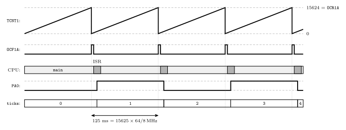
Figure 39: The example program running, one trace per signal. The count climbs to OCR1A = 15624 and is cleared (CTC mode), once every 125 ms. Each match sets OCF1A; the interrupt is enabled and I is 1, so the vector is taken a few cycles later, and taking it clears the flag again. The handler is a sliver of time in which the LED output is toggled and ticks counted, and the rest of the time belongs to main. Nothing in main looks at the timer. The LED blinks at 4 Hz, one toggle per match, however busy main is.
Priority
Priority is determined by vector: the lowest vector is the highest priority. RESET is highest, then INT0, and so on down the table. On the AVR, priority only matters when two or more interrupts are waiting to be serviced, and it decides which is taken first. It never lets one interrupt cut into another’s handler, because I is 0 throughout a handler. The datasheet adds one rule: after reti, the CPU always executes one instruction of the interrupted program before taking the next waiting interrupt, so a stream of interrupts can slow main down but never stop it altogether.
Interrupts can be re-enabled inside a handler with sei. Any incoming or waiting interrupt may then be serviced immediately, nested inside the current handler, even if it has lower priority. Priority plays no part there. Both cases are traced in 2026-09-21-interrupts and set against true priority nesting in polling-and-interrupts.
Pitfalls
- Forgetting
sei(). Everything else is set up, and nothing ever happens, because I is 0 from reset. - Enabling an interrupt that has no handler. In C, avr-libc fills every unused vector with a jump to a default handler that jumps to address 0, so the program restarts whenever the event occurs. It is not a true reset: the I/O registers keep whatever they held, which can make the restart behave differently from a power-up.
- Misspelling the vector name.
ISR(TIMER1_COMPA_Vect)compiles with only a warning, and the handler is never placed in the table, which makes it the previous pitfall. - Not clearing a stale flag before enabling: the interrupt fires once immediately, for an event that happened before the program was ready.
- Clearing a flag with
|=. If the compiler turns it into a read, an OR and a write, it clears every flag in the register that happens to be set (avr-timers-and-counters). Writing just the one bit,TIFR1 = (1<<OCF1A);, is safe however it is compiled. - In assembly: not saving
SREG, unbalanced pushes and pops, orretinstead ofreti. The first corrupts the interrupted code’s flags. The second returns to the wrong address. The third returns correctly but leaves I at 0, so no interrupt ever happens again. - Long handlers. No delay loops and no waiting inside an ISR: every other interrupt waits too, and repeated events of one source merge into one.
- A shared variable without
volatile, or a multi-byte one read withoutcli().
See also
- polling-and-interrupts — polling versus interrupts, the fourteen-step sequence, transparency, nesting policies, traps
- 2026-09-21-interrupts — Lecture 17: the stack revisited, worked questions,
volatiledrawn, priority traced - avr-timers-and-counters — the timer interrupt registers
TIMSKnandTIFRn, and the flags these interrupts replace polling - procedures-and-the-stack — the stack the return address goes on, and initialising
SP - avr-program-structure — the
jmp RESETtemplate the vector table extends - avr-architecture —
SREGand its I bit · avr-instructions — which instructions change the flags - c-preprocessor-and-avr-headers —
volatilein the I/O register macros · bit-masking —(1<<OCIE1A) - week8-lab-avr-timers — Lab 12, the timer set-up the example uses
- week9-lab-avr-interrupts — Lab 14: a stopwatch from a timer interrupt and two external interrupts
- software-timers — one timer interrupt keeping time for the whole program
- avr-usart — the three serial interrupts · analog-to-digital-conversion — the conversion-complete interrupt · avr-spi — the transfer-complete interrupt
AVR I/O Ports
How an AVR program actually reads a switch and lights an LED: the I/O register file, the three registers behind every port, the two instructions that reach them, how to change one bit of a port without disturbing the others, what writing to PINx really does, and the pins’ alternate uses by the serial interfaces. See avr-architecture for the chip these live on, avr-instructions for the instruction set, and io-board for the devices that get wired to the pins.
I/O registers
The ATmega324A has 224 I/O registers — registers that control the peripherals and carry data to and from them:
- Timers and counters
- Analog to digital converters
- Serial input/output
- General purpose input/output ports
They are not the general purpose registers. Some instructions work with these, others with r0–r31, and confusing the two is the standard beginner error — ldi r16, 0xFF and out DDRA, r16 name completely different register files with the same-looking numbers.
Some addresses are reserved (not actually available on this device). The full list is the I/O register summary, pages 636 to 639 of the datasheet.
Where they live, and how you get at them
I/O registers 0 to 223 sit in the data address space at memory addresses 32 to 255 (0x20 to 0xFF) — see memory-models for why the AVR has a separate data space at all. That gives two ways to name the same register, and two names for it:
| Range | Reached by | |
|---|---|---|
| First 64 I/O registers (0 to 63) | data addresses 0x20–0x5F |
in and out and ld/st |
| Other 160 — the “extended” I/O registers (64 to 223) | data addresses 0x60–0xFF |
ld/st only |
so the two numbering systems differ by a constant:
\[\text{data memory address} = \text{I/O register number} + \texttt{0x20}\]
The offset is exactly the 32 general purpose registers, which occupy 0x0000–0x001F at the bottom of the data space ahead of them.
Why the split exists at all: in/out encode the I/O register number in six bits of the instruction word, and \(2^6 = 64\). Everything past register 63 has no room in the encoding, so it can only be reached the long way round, by its data address.
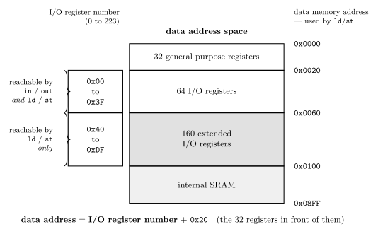
Figure 40: The bottom of the ATmega324A data address space, and the two numbering systems that live on it. Every I/O register has two numbers — its I/O register number (what in/out take) and its data memory address (what ld/st take) — and they differ by a constant 0x20, because the 32 general purpose registers sit in front of them in the same space. Only the first 64 I/O registers have an I/O register number small enough to fit the six operand bits of in/out; the 160 extended ones can be reached by their data address alone. The map follows the convention of csse2010-diagram-notation: lowest address at the top, hex addresses outside.
Extract from the I/O register list
The general purpose port registers are the first twelve entries, in the order PIN, DDR, PORT for each port in turn:
| Data address | I/O reg number | Name |
|---|---|---|
0x2B |
0x0B |
PORTD |
0x2A |
0x0A |
DDRD |
0x29 |
0x09 |
PIND |
0x28 |
0x08 |
PORTC |
0x27 |
0x07 |
DDRC |
0x26 |
0x06 |
PINC |
0x25 |
0x05 |
PORTB |
0x24 |
0x04 |
DDRB |
0x23 |
0x03 |
PINB |
0x22 |
0x02 |
PORTA |
0x21 |
0x01 |
DDRA |
0x20 |
0x00 |
PINA |
Further up the same list, to show the pattern continues and that reserved entries are real:
| Data address | I/O reg number | Name |
|---|---|---|
0x38 |
0x18 |
TIFR3 |
0x37 |
0x17 |
TIFR2 |
0x36 |
0x16 |
TIFR1 |
0x35 |
0x15 |
TIFR0 |
0x34 |
0x14 |
Reserved |
Read the two columns carefully in an exam question. out 0x02, r16 writes PORTA, but sts 0x02, r16 writes general purpose register r2 — the same number, two address spaces, and only the instruction tells them apart.
GPIO ports
The ATmega324A has four 8-bit general purpose I/O ports — PORT A, PORT B, PORT C, PORT D — appearing on the datasheet block diagram as PA7..0, PB7..0, PD7..0 around the edge of the chip, with port C drawn as PC5..0 plus TOSC1/PC6 and TOSC2/PC7 broken out separately — those two pins double as the timer oscillator connections. They are still port C bits, and DDRC/PORTC/PINC still cover all eight.
Three registers are associated with each (x = A, B, C or D):
| Register | Name | What it holds |
|---|---|---|
| DDRx | Data Direction Register | which pins are outputs |
| PORTx | values to output | |
| PINx | values on the pins |
Each is 8 bits — one bit per pin. DDRA0, PORTA0 and PINA0 are the three bits belonging to pin PA0.
What one bit of a port looks like
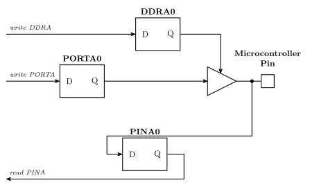
Figure 41: One bit of an AVR port — the three flip-flops behind pin PA0. DDRA0 enables the tri-state buffer, so it decides whether PORTA0’s value is driven onto the pin or the pin is left free for something outside to drive. PINA0 samples whatever is on the pin either way. Hence: DDR is direction, PORT is what you write, PIN is what you read.
1 means output, 0 means input. Writing 0xFF to DDRA makes every bit of port A an output, and writing 0x00 to DDRB makes every bit of port B an input.
Three consequences fall straight out of the circuit:
- PORTx does nothing on a pin whose DDRx bit is 0. The buffer is off; the value sits in the flip-flop unused. (On real AVR hardware it switches an internal pull-up instead.)
- PINx is always live. It samples the pin whether the pin is being driven from inside or outside, so reading PINx on an output pin reads back what you are driving.
- Reading PORTx is not reading the pin. It gives you the value you last wrote. To find out what is there, read PINx — which is why every input example uses
in rd, PINxand neverin rd, PORTx.
in and out
The two instructions that reach the first 64 I/O registers:
| Does | Operands | |
|---|---|---|
in rd, P |
Load I/O register value into general purpose register | rd: r0 to r31. P = I/O register number (0 to 63, 0x00 to 0x3F) or name |
out P, rr |
Store value from general purpose register into I/O register | rr: r0 to r31. P = 0 to 63 (0x00 to 0x3F) or name |
The operand order flips between them, and it flips for a consistent reason: like every AVR instruction, the destination is written first. So the I/O register is the second operand of in and the first of out.
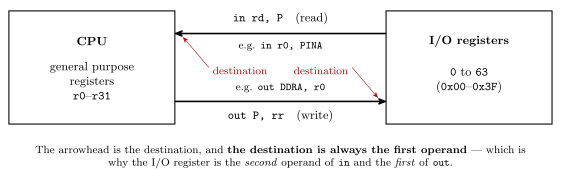
Figure 42: in and out between the two register files: the CPU’s general purpose registers r0–r31 and the first 64 I/O registers. in reads from an I/O register into a general purpose register, out writes the other way, and the head of each arrow, marked destination, is the operand written first. That is why the I/O register is the second operand of in and the first of out.
Answers of the form in DDRB, r16 are the standard trap. What is wrong with them is the mnemonic, not the direction: in’s destination is always one of r0–r31, so it can never be DDRB. Moving a general purpose register into an I/O register is exactly what out does — which is why the right answer in that shape is out DDRB, r16.
in and out reach all 32 general purpose registers, r0–r31 — unlike ldi, they are not restricted to the top half.
Both are one instruction word and one clock cycle, which makes them the cheapest way to touch a peripheral.
Three equivalences, all of them just the number/name table above:
| Written with a number | Same instruction, written with a name |
|---|---|
in r0, 0 |
in r0, PINA |
out 1, r0 |
out DDRA, r0 |
in r5, 0x26 |
in r5, TCNT0 — I/O register 0x26 is timer/counter 0 |
Using port names
Numbers are how the machine sees it; names are how you should write it:
.include "m324Adef.inc"The contents of this file are included directly in the program, and it defines the names for the I/O registers — so DDRA, PORTA, PINA, TCNT0 and the rest can be written instead of 0x01, 0x02, 0x00, 0x26. Everything about the generated machine code is identical; the assembler substitutes the number.
Setting port A (all bits) to be an output, which is the shape of nearly every initialisation block:
    ldi  r16, 0xFF       ; every bit 1 = output
    out  DDRA, r16       ; ... into the direction register
or, using the shorthand of avr-instructions, ser r16 in place of the ldi. Setting a port to be all inputs is the same two lines with 0x00 (or clr), and a mixed port is any other constant — DDRA is a bit pattern like everything else, so ldi r16, 0x0F gives four outputs and four inputs.
Changing one bit of a port
Writing a whole port register is right at initialisation. Afterwards a program usually wants to change one pin and leave the other seven alone, because the other pins belong to other parts of the program. In C that is a read-modify-write with a one-bit mask, the bit named rather than given as a number (bit-masking):
DDRC  |= (1<<5);          /* PC5 becomes an output     */
PORTC |= (1<<5);          /* PC5 driven high           */
PORTC &= ~(1<<5);         /* PC5 driven low            */
PORTC ^= (1<<5);          /* PC5 flipped               */
if (PINC & (1<<2)) { }    /* is PC2 high?              */
In assembly there are two ways:
| Register | Set or clear one bit | |
|---|---|---|
I/O registers 0 to 31, which includes every PINx, DDRx and PORTx |
sbi PORTC, 5 and cbi PORTC, 5 |
one instruction, other bits untouched |
any register in/out reach, 0 to 63 |
in r16, TCCR0B, then ori or andi with the mask, then out TCCR0B, r16 |
three instructions, and a spare register |
sbi and cbi hold the register number in five bits of the instruction, so they reach only the first 32 I/O registers. TCCR0B is I/O register 0x25, 37, which is past them: the long way is the only way. The extended registers past 63, such as TIMSK2 and TCCR1B, need lds and sts in place of in and out.
Writing to PINx
PINx is the port’s input register: reading it gives the levels on the pins. Writing to it is not storing a value. On the ATmega324A, writing a 1 to a bit of PINx toggles the matching bit of PORTx, whatever the pin’s direction, and writing a 0 does nothing.
That makes PINx a quick way to flip a pin:
PINC = (1<<0); /* toggle PC0; the 0s written to the other bits do nothing */and in assembly sbi PINC, 0 does the same in one instruction.
It also makes PINx the wrong register for a clear or a set. PINC &= ~(1<<5) does not clear PC5. If the compiler turns it into a single cbi PINC, 5, it writes a 0 to bit 5 of PINC and nothing happens. If it does a read, an AND and a write, it writes 1s to every other bit that read high, and those pins flip:
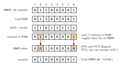
Figure 43: Why a read-modify-write on PINC goes wrong. Port C is all outputs, driving 0110 0001, so its pins read the same. PINC &= ~(1<<5) reads them, clears bit 5 of the reading and writes the result to PINC. A 1 written to a PINx bit is an order to toggle that bit of PORTx, not a value to keep, and a 0 does nothing. So the two other 1s, shaded, flip PC6 and PC0 low, and PC5, the bit meant to be cleared, stays high. The bottom row is what PORTC &= ~(1<<5) would have given.
So: set and clear through PORTx, read through PINx, and write PINx only to toggle.
Alternate pin functions
Most pins have a second job. When the peripheral that owns a pin is switched on, it takes the pin over from the port, and for some pins it overrides DDRx too. The serial interfaces use these:
| Port pin | Package pin | Alternate use | Peripheral |
|---|---|---|---|
| PB0 | 1 | XCK0 | USART0’s clock, used when it is an SPI master |
| PB4 | 5 | \(\overline{\text{SS}}\) | SPI (avr-spi) |
| PB5 | 6 | MOSI | SPI |
| PB6 | 7 | MISO | SPI |
| PB7 | 8 | SCK | SPI |
| PC0 | 22 | SCL | TWI |
| PC1 | 23 | SDA | TWI |
| PD0 | 14 | RXD0 | USART0 (avr-usart) |
| PD1 | 15 | TXD0 | USART0 |
| PD2 | 16 | RXD1 | USART1 |
| PD3 | 17 | TXD1 | USART1 |
| PD4 | 18 | XCK1 | USART1’s clock, used when it is an SPI master |
So the SPI port is the upper half of port B, and the TWI is the bottom two bits of port C. Other pins carry timer outputs, the external interrupts (INT0 and INT1 share PD2 and PD3 with USART1) and, on port A, the analog inputs. A pin can do only one job at a time, so a program that uses the SPI cannot also use PB4 to PB7 as general purpose I/O. The whole pinout is drawn in 2026-10-05-more-io.
Common mistakes
in DDRB, r16.inalways writes a general purpose register. Writing an I/O register isout DDRB, r16.- Reading
PORTxto find out what is on a pin. That gives back what was last written. The pins arePINx. - Setting or clearing a bit through
PINx. A 1 written there toggles, soPINC &= ~(1<<5)flips other pins and leaves PC5 alone. PORTC = (1<<5)to set one pin.=writes all eight bits and drives the other seven low. Use|=.sbiorcbion a register past 31, such asTCCR0B. They cannot reach it; usein,ori/andi,out.- Using a pin as general I/O while its peripheral is on. The SPI, the TWI and the USARTs take their pins over.
See also
- avr-architecture — the data address space these sit in, and the rest of the chip
- avr-instructions · avr-program-structure · bit-masking
- memory-models — why the I/O registers have two addresses
- io-board · device-pinouts — the switches, LEDs and buttons wired to the pins
- week6-lab-avr-io-ports — Lab 10, where this gets wired up
- avr-usart — PD0 and PD1 as a serial port · analog-to-digital-conversion — port A as analog inputs
- avr-spi — PB4 to PB7 as the SPI port · serial-communication — the TWI on PC0 and PC1
- 2026-08-31-instruction-set-architecture-part-1 — Lecture 11 · 2026-10-05-more-io — Lecture 19
AVR Assembly Program Structure
The skeleton every AVR assembly program in this course is built on — what goes at the top, where execution starts, and why it ends in an infinite loop. See avr-instructions for what fills it in and avr-io-ports for what the initialisation section usually does.
The template
                             ; Comments start with semicolons
.include "m324Adef.inc"

    jmp RESET                ; <- vector table
    ; Interrupt handlers go here
    ; (more on this in week 9/10)

RESET:                       ; Starting point   <- RESET handler
    ...                      ; Initialisation code
                             ; e.g. set DDRs

loop:                        ; <- main code
    ...                      ; Do stuff
    jmp loop                 ; Repeat
Three sections, and each is there for a reason:
| Section | What it is |
|---|---|
| Vector table | jmp RESET, then the interrupt handlers |
| RESET handler | the starting point — initialisation code, e.g. setting the data direction registers |
| Main code | the work, ending in a jump back to its own label |
Why the vector table comes first
The chip begins executing at program address 0x0000 — the top of the program memory map in memory-models — and the addresses immediately after it are reserved for interrupt vectors, one per interrupt source. So the very first instruction has to jump over them to reach the real start of the program. That is all jmp RESET is doing.
Everything between that jump and the RESET: label is the vector table itself. It stays empty (comments only) in a program that uses no interrupts — but the jmp has to be there from the first program, because without it execution would fall straight into whatever occupied the vector slots. Once a program does use an interrupt, each vector slot it needs holds a jmp to that source’s handler at a fixed address, placed with .org; the table, the handlers and how to enable them are in avr-interrupts.
Labels and jmp
A label is a name for a position in the program:
        jmp RESET
        …
RESET:  …
        …

loop:   …
        …
        jmp loop
The assembler replaces each label with the program-memory address it ended up at, so jmp loop becomes a jump to a real address. Two properties matter in practice:
- A label is written at the start of the line, ending in a colon; the instruction it names can be on the same line or the next one.
- Labels let you write code without ever computing an address by hand, which is most of what an assembler buys you over machine code (instruction-set-architecture).
jmp RESET at the top of the template needs the address of a label the assembler has not reached yet. It copes by reading the file twice: the first pass only works out where every label lands, using each line’s size, and the second fills the addresses into the instructions (assembly-process). In the template RESET is the address straight after the vector table, worked out the same way.
jmp itself is unconditional. For jumping only sometimes, the branch instructions below take a label in exactly the same way.
Conditional control flow
A branch instruction takes a label just as jmp does, but jumps only if a status register bit says so — so a decision is always written as two instructions, one that sets the flags and one that reads them:
breq label |
branch if Z = 1 |
brne label |
branch if Z = 0 |
The usual flag-setter is cp, which is a subtraction whose result is not saved: it computes rd - rr purely to set Z, N, C, V and the rest, so cp r5, r6 followed by breq branches exactly when the two registers were equal. The instruction reference specifies which status register bits are set by which instructions, per instruction rather than by one general rule — so a compare is not always needed, because whatever ran last may already have set Z. avr-instructions tabulates which does what.
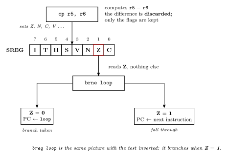
Figure 44: Compare-then-branch: the whole of an AVR conditional. cp performs the subtraction and throws the difference away, keeping only what it did to the flags; brne then reads exactly one of them and either loads the label’s address into the program counter or lets execution fall through to the next instruction. The flag names and their order are those of the AVR status register; the outline on Z marks the one flag brne tests.
Figure 44 is worth reading as the reason labels matter. The branch does not encode “go back three instructions” in a form you have to count out by hand; it names a label, and the assembler works out the address — the same service it performs for jmp RESET at the top of the file.
Two consequences for the template above. First, a loop that should sometimes end is still written as a label plus a branch, not as a special construct: the body falls through when the condition fails. Second, nothing may sit between the flag-setter and the branch that disturbs the flag being tested — the status register is a single shared piece of state, and the instruction in between will happily overwrite it.
The two branches above are the equality pair. The other eight — including the signed and unsigned less than pairs that a loop bound usually needs — and the loop idioms built from them are in avr-branches-and-jumps.
When the program calls procedures
The template above has no stack, because nothing in it calls anything. The moment a program uses call or rcall — or push — the stack pointer must be set first, and it goes at the top of RESET:, before any of the other initialisation:
RESET:
    ldi  r16, low(RAMEND)
    out  SPL, r16
    ldi  r16, high(RAMEND)
    out  SPH, r16
    ...                      ; then set DDRs and the rest as before
RAMEND is the last SRAM address, 0x08FF; the stack starts there and grows downward. Why it has to, and what call and ret do with it, is procedures-and-the-stack. A C program gets these four instructions for free from the compiler’s start-up code.
Variables and constants
The template holds only code. Variables and tables of constants go in the other segments (assembly-process), chosen by .dseg and .cseg:
.include "m324Adef.inc"
.def    temp = r16              ; a name for a register

        .dseg                   ; SRAM: space only
count:  .byte 1                 ; one byte, at 0x0100

        .cseg                   ; flash: code and constants
        jmp  RESET              ; vector table
RESET:
        ldi  temp, low(RAMEND)  ; stack pointer, if anything is called
        out  SPL, temp
        ldi  temp, high(RAMEND)
        out  SPH, temp
        ...                     ; initialisation
loop:
        ...                     ; main code
        jmp  loop

digits: .db  63, 6, 91, 79, 102, 109, 125, 7, 127, 111   ; seven-segment patterns, 0 to 9
Three rules come with it:
- A variable is a label on a
.bytein the data segment. It gets an address,0x0100for the first one, but no value. The program has to store something there, withsts count, tempfor example, before reading it. - Constants go in the code segment, out of the path of execution. The CPU runs whatever is in program memory at the PC, so a table in the middle of the code would be executed as if it were instructions. After the main loop’s
jmp loopis safe, because execution never gets there. Betweenjmp RESETandRESET:is safe for the same reason, but only in a program that uses no interrupts, because that is where the interrupt vectors go.digitsis ten bytes, an even number, so it fills five words with no pad (assembly-process). - A constant is read with
lpm, at its byte address, the label times 2, in Z (memory-models).
Why it ends in an infinite loop
loop: … jmp loop is not a placeholder. A microcontroller program has nowhere to return to — there is no operating system underneath it, and the CPU keeps fetching whatever comes next for as long as it has power. So the main body of an AVR program is a loop that never exits, and “do this repeatedly”, which is how nearly every lab task is worded, is the normal shape rather than a special case.
The division of labour that follows: anything that should happen once goes in the RESET handler (setting DDRs, loading constants), and anything that should happen forever goes in the loop (reading inputs, computing, writing outputs).
See also
- avr-branches-and-jumps — the full branch table, jumps, and the
if/loop idioms · procedures-and-the-stack —call,retand the stack - avr-interrupts — what goes in the vector table, and the handlers after it
- avr-instructions · avr-io-ports · avr-architecture
- assembly-process — statement fields, directives, segments and the two-pass assembler · instruction-set-architecture — assembly, the assembler and the toolchain
- memory-models — the program address space the vector table sits at the bottom of · memory-technologies — flash and SRAM, the memories behind
.csegand.dseg - week6-lab-avr-io-ports — Lab 10, where the template is first used
- 2026-10-08-assembly-process — Lecture 20: how the assembler turns the template into machine code
SPI on the AVR
The Serial Peripheral Interface, and the ATmega324A’s SPI port: the four signals, how two shift registers exchange a byte, one transfer in time, the ways to connect several slaves, the pins, the three registers, the clock rate, code to send and receive, the interrupt, and the USARTs as extra SPI masters. Where SPI sits among serial links, next to the UART and I²C, is in serial-communication. First met in 2026-10-05-more-io. The datasheet covers the SPI on pages 166 to 174.
What SPI is
SPI is a synchronous serial bus with one master and one or more slaves (serial-communication).
- Synchronous: the master sends a clock, and both ends move a bit on each pulse of it. Nothing about speed has to be agreed beforehand, except that the master must not go faster than the slave can follow.
- Full duplex: there is a data wire in each direction, and every clock pulse moves one bit each way.
- The master starts every transfer and makes the clock. A slave only answers.
| Signal | Driven by | Carries |
|---|---|---|
| SCK (also written SCLK) | master | serial clock, one pulse per bit |
| MOSI | master | Master Out, Slave In |
| MISO | slave | Master In, Slave Out |
| \(\overline{\text{SS}}\) | master | Slave Select, active low: a slave takes part only while its \(\overline{\text{SS}}\) is 0 |
The names say which end drives each wire, so the wiring is MOSI to MOSI and MISO to MISO. It is not crossed over the way a UART’s Tx and Rx are.
The exchange: two shift registers in a ring
Master and slave each have an 8-bit shift register (shift-registers). MOSI joins the master’s MSB end to the slave’s LSB end, and MISO joins the slave’s MSB end to the master’s LSB end. Together they are one 16-bit register bent into a ring, and each SCK pulse rotates it by one place. The hardware view, with the clock generator and the select pins, is drawn in 2026-10-05-more-io.
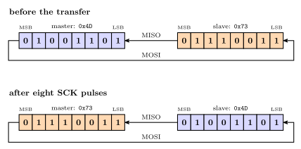
Figure 45: The exchange as data. Before the transfer the master’s register holds 0x4D, shaded blue, and the slave’s holds 0x73, shaded orange. Each SCK pulse moves every bit one place round the ring: towards the MSB inside each register, and across on MOSI or MISO at the ends. After eight pulses each byte has gone all the way across and the shading has changed sides: the master holds 0x73 and the slave 0x4D. A byte has been sent in each direction at once.
Two consequences follow from the ring:
- To receive, the master must send. There is no read-only transfer. To collect a byte from a slave, the master sends a dummy byte, often
0x00or0xFF, and keeps what comes back. - To send is also to receive. Every byte sent brings one back. If it is of no interest, the master reads it and throws it away.
Worked: one exchange, clock by clock
The master’s register holds 0x4D (0100 1101) and the slave’s holds 0x73 (0111 0011), and the bytes go most significant bit first. Each clock, each register’s top bit leaves on its data wire, the other seven move up one place, and the bit arriving from the other end fills the bottom:
| After clock | MOSI carried | MISO carried | Master | Slave |
|---|---|---|---|---|
| start | 0100 1101 |
0111 0011 |
||
| 1 | 0 | 0 | 1001 1010 |
1110 0110 |
| 2 | 1 | 1 | 0011 0101 |
1100 1101 |
| 3 | 0 | 1 | 0110 1011 |
1001 1010 |
| 4 | 0 | 1 | 1101 0111 |
0011 0100 |
| 5 | 1 | 0 | 1010 1110 |
0110 1001 |
| 6 | 1 | 0 | 0101 1100 |
1101 0011 |
| 7 | 0 | 1 | 1011 1001 |
1010 0110 |
| 8 | 1 | 1 | 0111 0011 |
0100 1101 |
The MOSI column, read down, is 0100 1101, the master’s byte, and the MISO column is 0111 0011, the slave’s. After 8 clocks the master holds 0x73 and the slave 0x4D.
One transfer in time
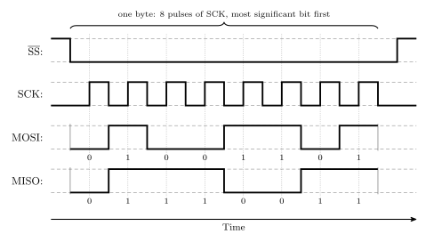
Figure 46: One SPI transfer in the AVR’s default mode: SCK idles low, both ends sample their incoming data wire on each rising edge of SCK (the dotted lines), and both put out their next bit on each falling edge. The master pulls \(\overline{\text{SS}}\) low to select the slave, and the slave’s first bit appears on MISO at that moment. Eight clock pulses then carry 0x4D from master to slave on MOSI and 0x73 from slave to master on MISO, most significant bit first, with the bit values written under each data wire. Raising \(\overline{\text{SS}}\) ends the transfer. The data wires matter only while \(\overline{\text{SS}}\) is low, so they are drawn only then.
A transfer, from the master’s side:
- Pull \(\overline{\text{SS}}\) low. The selected slave wakes up and puts its first bit on MISO.
- Write the byte to the data register. The SPI hardware makes eight pulses on SCK. On each rising edge both ends read the data wire coming in; on each falling edge both shift their next bit out.
- Wait for the transfer-complete flag, then read the byte that came in.
- Send more bytes the same way, or raise \(\overline{\text{SS}}\) to end the transfer.
The AVR’s SPI hardware never moves \(\overline{\text{SS}}\) itself in master mode. Steps 1 and 4 are the program’s job, done with PORTB.
Clock polarity and phase
The figure shows the AVR’s mode after reset. Two bits in the control register change it: CPOL, which level SCK rests at, and CPHA, whether data is read on the first or the second edge of each pulse. Together they number four modes:
| Mode | CPOL | CPHA | SCK when idle | Data read on |
|---|---|---|---|---|
| 0 | 0 | 0 | low | the rising edge, the first of each pulse |
| 1 | 0 | 1 | low | the falling edge, the second of each pulse |
| 2 | 1 | 0 | high | the falling edge, the first of each pulse |
| 3 | 1 | 1 | high | the rising edge, the second of each pulse |
A third setting is the bit order, MSB first or LSB first. A device’s datasheet says which mode and bit order it uses, and the master has to match it. As with a UART’s settings (serial-communication), nothing on the wires says which is in use, and a mismatch gives wrong bytes, not an error.
Several slaves
Both wirings are drawn in 2026-10-05-more-io.
Independent selects. SCK and MOSI go to every slave, and every slave’s MISO joins the one wire back to the master. Each slave has its own select line from the master, and the master pulls one low at a time. A slave whose \(\overline{\text{SS}}\) is high ignores SCK and lets go of MISO (the AVR as a slave makes all its SPI pins inputs), so only the selected slave drives the shared wire. Every slave costs one more master pin.
Daisy chain. One select line goes to all the slaves, and the data passes through them in turn: master MOSI into slave 1’s MOSI, each slave’s MISO into the next one’s MOSI, the last slave’s MISO back to the master’s MISO. The master’s register and the slaves’ registers make one ring, \(8 \times (\text{slaves} + 1)\) bits round. A chainable device acts on the byte it holds when \(\overline{\text{SS}}\) goes back high, so everything has to be in place by then.
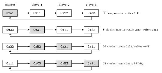
Figure 47: A daisy chain of three slaves as one long shift register, 32 bits round. Each row is the chain at one moment, read left to right in the direction the data moves, and the arrow underneath is the last slave’s MISO returning to the master. Shaded bytes are the ones the master has sent. Every 8 clocks move every byte one place along, so the first byte sent, 0xA1, ends up in the farthest slave, and the master receives the slaves’ old bytes, the farthest slave’s first. Between bytes the master reads what has arrived and writes the next byte to send.
Worked: which byte goes first?
To leave 0xA1 in slave 3, 0xB2 in slave 2 and 0xC3 in slave 1, send 0xA1, 0xB2, 0xC3, in that order, with \(\overline{\text{SS}}\) low for all 24 clocks. The byte for the farthest slave goes first, because every later byte pushes it one place further along. The three bytes that come back are the slaves’ previous contents, slave 3’s first.
The pins
The SPI port uses the upper half of port B (avr-io-ports):
| Port pin | Package pin | Signal | As master | As slave |
|---|---|---|---|---|
| PB4 | 5 | \(\overline{\text{SS}}\) | the program’s to use: make it an output | input |
| PB5 | 6 | MOSI | output: the program sets its DDRB bit |
input |
| PB6 | 7 | MISO | input | output: the program sets its DDRB bit |
| PB7 | 8 | SCK | output: the program sets its DDRB bit |
input |
Switching the SPI on forces some pins’ directions and leaves others to DDRB. A pin marked input is made an input by the hardware. A pin that has to be an output, the program has to make an output itself.
The \(\overline{\text{SS}}\) pin in master mode. If PB4 is left as an input and something pulls it low, the AVR takes it that another master is selecting it as a slave. It clears MSTR0, becoming a slave, and sets the transfer-complete flag. A master therefore makes PB4 an output, usually as the select line for its slave, or else guarantees that it stays high. As an output it is an ordinary port pin and the SPI ignores it.
These same pins are the ones a programmer uses to download a program into the AVR, which is worth remembering when a device is attached to them.
The registers
| Register | Holds |
|---|---|
SPCR0 |
control: on/off, master or slave, bit order, clock mode, clock rate, interrupt enable |
SPSR0 |
status: the transfer-complete and write-collision flags, and the double-speed bit |
SPDR0 |
data: write a byte to send it, read the byte received |
The datasheet’s SPI chapter (pages 172 and 173) calls these SPCR, SPSR and SPDR, and its bit names have no 0 either. In C and assembly every name carries the 0: SPCR0, SPE0, MSTR0, SPIF0, and SPR1 becomes SPR10. The I/O register summary still names the registers SPCR and SPSR, but writes the bit names with the 0, except that it labels bit 1 SPR01 where the header has SPR10.
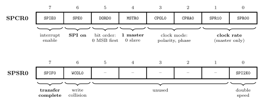
Figure 48: The SPI port’s two control and status registers, with the names used in code. SPCR0 sets the port up: bit 6 turns it on, bit 4 chooses master or slave, bit 5 the bit order, bits 3 and 2 the clock mode, and the bottom two bits the clock rate when it is a master. Bit 7 lets the end of a transfer raise an interrupt. In SPSR0, bit 7 is the flag that says a transfer has finished, bit 6 reports a write to the data register in the middle of a transfer, and bit 0 doubles the master’s clock rate, a third clock-rate bit to go with the two in SPCR0. Every bit is 0 after reset, so the port starts switched off.
SPCR0: the set-up
| Bit | Name | When 1 | When 0 |
|---|---|---|---|
| 7 | SPIE0 |
the end of a transfer raises an interrupt | no interrupt |
| 6 | SPE0 |
the SPI port is on | off: the pins belong to port B |
| 5 | DORD0 |
LSB first | MSB first |
| 4 | MSTR0 |
master | slave |
| 3 | CPOL0 |
SCK idles high | SCK idles low |
| 2 | CPHA0 |
data read on the second edge of each pulse | data read on the first edge |
| 1:0 | SPR10, SPR00 |
the clock rate, with SPI2X0 (below) |
SPSR0: what has happened
| Bit | Name | Set when | Cleared by |
|---|---|---|---|
| 7 | SPIF0 |
a transfer has finished; also when a master’s \(\overline{\text{SS}}\) input is pulled low | the interrupt handler running, or reading SPSR0 and then SPDR0 |
| 6 | WCOL0 |
SPDR0 was written while a transfer was going on |
reading SPSR0 and then SPDR0 |
| 0 | SPI2X0 |
(a setting) 1 doubles the master’s SCK |
Bits 5 to 1 are unused.
SPDR0: the data
Writing SPDR0 starts a transfer when the port is a master: the byte goes into the shift register and the eight clock pulses begin. Reading SPDR0 gives the byte received. The two directions are buffered differently. On the way out there is only the shift register, so a byte written during a transfer is not sent and sets WCOL0 instead. On the way in the finished byte is copied to a buffer, where it waits until the next byte is complete, so it has to be read before then or it is lost.
Choosing the clock rate
In master mode three bits pick the divider:
SPI2X0 |
SPR10 |
SPR00 |
SCK | At 8 MHz |
|---|---|---|---|---|
| 0 | 0 | 0 | \(f_{OSC}/4\) | 2 MHz |
| 0 | 0 | 1 | \(f_{OSC}/16\) | 500 kHz |
| 0 | 1 | 0 | \(f_{OSC}/64\) | 125 kHz |
| 0 | 1 | 1 | \(f_{OSC}/128\) | 62.5 kHz |
| 1 | 0 | 0 | \(f_{OSC}/2\) | 4 MHz |
| 1 | 0 | 1 | \(f_{OSC}/8\) | 1 MHz |
| 1 | 1 | 0 | \(f_{OSC}/32\) | 250 kHz |
| 1 | 1 | 1 | \(f_{OSC}/64\) | 125 kHz |
SPI2X0 halves the divider chosen by the other two. Eight codes give seven dividers, because 64 appears twice. After reset all three bits are 0, which is divider 4.
In slave mode these bits do nothing, because the slave’s clock comes from the master. A slave samples the incoming SCK with its own clock and is only guaranteed to keep up to \(f_{OSC}/4\), 2 MHz at 8 MHz.
A byte takes 8 SCK periods, which is \(8 \times\) divider CPU cycles: 16 cycles (2 µs) at the fastest, 1024 (128 µs) at the slowest.
Worked: the slowest master clock
Which bits must be 1 to switch the SPI on as a master with the slowest clock, and what is written to SPCR0?
The slowest divider is 128, code SPI2X0 SPR10 SPR00 = 0 1 1. Add SPE0 to switch the port on and MSTR0 to make it a master. Nothing in SPSR0 needs to be 1, since SPI2X0 must stay 0.
SPCR0 = (1<<SPE0) | (1<<MSTR0) | (1<<SPR10) | (1<<SPR00); /* 0101 0011 = 0x53 */Bits 6, 4, 1 and 0 make 0100 0000 + 0001 0000 + 0000 0010 + 0000 0001 = 0x53, and SCK is \(8\text{ MHz}/128 = 62.5\) kHz.
Worked: a 1 MHz clock
\(8\text{ MHz}/1\text{ MHz} = 8\), which is code 1 0 1: SPR00 in SPCR0 and SPI2X0 in SPSR0.
SPCR0 = (1<<SPE0) | (1<<MSTR0) | (1<<SPR00);
SPSR0 = (1<<SPI2X0);
Sending and receiving, by polling
A master that sends and receives one byte at a time:
#include <avr/io.h>

#define SS_PIN 4                          /* PB4 used as the slave's select */

void spi_init_master(void) {
    DDRB  |= (1<<SS_PIN) | (1<<5) | (1<<7);   /* SS, MOSI, SCK outputs; MISO stays an input */
    PORTB |= (1<<SS_PIN);                     /* SS high: no slave selected yet             */
    SPCR0  = (1<<SPE0) | (1<<MSTR0) | (1<<SPR00);   /* on, master, f/16 = 500 kHz        */
}

uint8_t spi_exchange(uint8_t out) {
    SPDR0 = out;                          /* writing starts the eight clocks   */
    while (!(SPSR0 & (1<<SPIF0))) {       /* wait for the transfer to finish   */
    }
    return SPDR0;                         /* the byte that came back; reading  */
                                          /* SPSR0 then SPDR0 clears SPIF0     */
}
and a transfer of two bytes, the second one to collect the slave’s reply:
uint8_t reply;

PORTB &= ~(1<<SS_PIN);                    /* select the slave                */
spi_exchange(0x4D);                       /* send; what comes back is ignored */
reply = spi_exchange(0x00);               /* send a dummy byte to read one   */
PORTB |= (1<<SS_PIN);                     /* deselect                        */
The rules it follows:
- The program moves \(\overline{\text{SS}}\), low before the first byte and high after the last.
- One byte at a time. Write
SPDR0, wait forSPIF0, then write the next. A write during a transfer is lost. - To read, send.
At 500 kHz the wait is 16 µs, 128 CPU cycles, against about a millisecond for a UART frame at 9600 baud. Waiting by polling (polling-and-interrupts) is often the sensible choice for SPI.
As a slave, the AVR only makes MISO an output and switches the port on with MSTR0 left at 0:
void spi_init_slave(void) {
    DDRB |= (1<<6);                       /* MISO is the slave's one output */
    SPCR0 = (1<<SPE0);                    /* on, slave                      */
}
A slave can never start anything. It puts the reply it wants to give in SPDR0 ahead of time, and when the master has clocked a byte through, SPIF0 is set and SPDR0 holds what the master sent.
The interrupt
| Event | Flag (SPSR0) |
Enable (SPCR0) |
Handler |
|---|---|---|---|
| transfer complete | SPIF0 |
SPIE0 |
ISR(SPI_STC_vect) |
It is vector 20 in the table (avr-interrupts), and running the handler clears SPIF0. The usual use is a queue of bytes: the handler reads the byte that has just arrived and writes the next one to SPDR0, so a run of bytes goes out without the main program waiting on each. On a slave, the interrupt is how the program finds out that the master has just exchanged a byte with it.
The USARTs as SPI masters
Each USART can also work as an SPI master, by setting its mode bits UMSELn1:0 in UCSRnC to 11 (avr-usart). Its pins then take the SPI roles:
| USART | SCK | Data out (MOSI) | Data in (MISO) |
|---|---|---|---|
| USART0 | XCK0, PB0 | TXD0, PD1 | RXD0, PD0 |
| USART1 | XCK1, PD4 | TXD1, PD3 | RXD1, PD2 |
There is no select pin: the program drives any spare port pin as \(\overline{\text{SS}}\). A USART in this mode can only be a master. With the SPI port as well, the ATmega324A can be the master on three separate SPI buses.
Common mistakes
- Crossing MOSI and MISO as if they were a UART’s Tx and Rx. MOSI goes to MOSI.
- Expecting to read without sending. The master gets a byte only by sending one.
- Leaving PB4 an input in master mode. If it floats or is pulled low,
MSTR0is cleared and the AVR silently becomes a slave. - Not setting
DDRBfor MOSI and SCK on a master, or MISO on a slave. Switching the SPI on does not make those pins outputs. - Waiting for the hardware to drive \(\overline{\text{SS}}\). A master has to do it in software.
- Writing
SPDR0before the last transfer has finished. The byte is not sent andWCOL0is set. - Using the datasheet names
SPCR,SPE,SPR1in code. The header names have a0:SPCR0,SPE0,SPR10. - Mismatched mode or bit order with the slave device: wrong bytes and no error.
- Clocking an AVR slave faster than \(f_{OSC}/4\).
- Loading a daisy chain nearest slave first. The first byte sent ends up in the farthest slave.
See also
- serial-communication — SPI next to the UART and I²C, bus masters and slaves, bit bashing
- shift-registers — the register at each end of the ring
- avr-io-ports — port B,
DDRB, and the pins’ alternate functions - avr-usart — the USART, and its mode bits for master SPI
- avr-interrupts · polling-and-interrupts — the
SPI_STCinterrupt, or waiting onSPIF0 - bit-masking · c-preprocessor-and-avr-headers —
(1<<SPE0)and where the names come from - week10-lab-adc-and-spi — Lab 16, the SPI port driving an LED matrix
- 2026-10-05-more-io — Lecture 19
AVR Timers and Counters
The ATmega324A’s three timer/counter units: what they are, which pins and registers belong to each, how their clock is chosen and prescaled, the modes that decide what the count does when it reaches its top, the output compare actions that let a match drive a pin, and the one formula that turns a wanted event frequency into register values. From 2026-09-14-flow-of-control and 2026-09-17-pulse-width-modulation, with the register-level detail from week8-lab-avr-timers. PWM, the timers’ main use, has its own note: pulse-width-modulation.
Timer, counter
- A counter is a binary up/down counter clocked on some event.
- A timer is a counter clocked by a regular clock.
One piece of hardware, two names for what its clock is. Clock it from an external pin and each count is an event; clock it from the system clock and each count is a fixed slice of time, so the count is elapsed time. It is the wide, fast, silicon version of the counters of counters, and it is separate hardware from the CPU: once configured it counts, compares and drives its pins with no instructions running, which is the whole reason to have it.
Three things a timer/counter is used for, in this course:
| Use | Clock | The event |
|---|---|---|
| Timing — do something every 100 ms, toggle an LED, tick a clock | system clock ÷ prescaler | the count reaching a compare value or wrapping, at a known interval |
| Counting — how many pulses arrived on a pin | edges on the external pin Tn |
the count reaching a compare value: that many pulses |
| PWM — an adjustable-width pulse on a pin, in hardware | system clock ÷ prescaler | the compare match switching the OCnx pin partway through each sweep |
The three units
| Timer/Counter 0 | Timer/Counter 1 | Timer/Counter 2 | |
|---|---|---|---|
| Width | 8-bit (0–255) | 16-bit (0–65535) | 8-bit (0–255) |
| Output compare pins | PB3 = OC0A, PB4 = OC0B |
PD5 = OC1A, PD4 = OC1B |
PD7 = OC2A, PD6 = OC2B |
| External clock pin | PB0 = T0 |
PB1 = T1 |
none — TOSC1/TOSC2 (PC6/PC7) take a separate crystal instead |
| Prescaler taps | 1, 8, 64, 256, 1024 | 1, 8, 64, 256, 1024 | 1, 8, 32, 64, 128, 256, 1024 |
| Modes | Normal, CTC, Fast PWM, Phase Correct PWM | Normal, CTC, Fast PWM, PC PWM, PFC PWM | Normal, CTC, Fast PWM, Phase Correct PWM |
| Count register | TCNT0 |
TCNT1H:TCNT1L |
TCNT2 |
| Control registers | TCCR0A, TCCR0B |
TCCR1A, TCCR1B, TCCR1C |
TCCR2A, TCCR2B |
| Compare registers | OCR0A, OCR0B |
OCR1AH:OCR1AL, OCR1BH:OCR1BL |
OCR2A, OCR2B |
| Interrupt registers | TIMSK0, TIFR0 |
TIMSK1, TIFR1 |
TIMSK2, TIFR2 |
Every unit has two compare units, A and B, each with its own register and its own pin. Timer 1 is the one to reach for when 255 is not enough: its 16 bits give periods 256 times longer at the same prescaler, and it is the timer Lab 12 sets up. Timer 2 is the one with a separate clock source, for real-time-clock use. The T/C 3 in the family datasheet’s block diagram is on the ATmega1284, not this chip (avr-architecture).
The pins are shared with GPIO. OC0A is PB3 until timer 0 is told to drive it; configuring a compare output takes the pin away from PORTB and hands it to the timer. The DDR bit must still be set to output, since the timer only decides what the pin shows, not whether it drives.
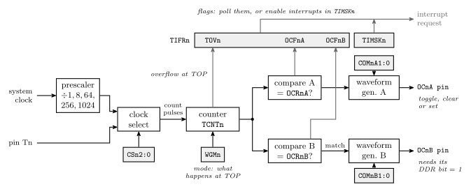
Figure 49: One timer/counter unit, from clock to pins. The clock select multiplexer feeds the counter either a prescaler tap or an edge on the external pin, or nothing; the counter increments on each pulse of whatever it is given. Two compare registers are each checked against the count every tick, and a match raises that unit’s flag and fires the waveform generator for its pin. Reaching the top of the count raises the overflow flag and, depending on the mode, wraps the count. The flags collect in TIFRn, where a program can poll them or, with the matching bits set in TIMSKn, have them raise an interrupt. Every box is configured through I/O registers and then runs with no CPU involvement.
Registers: data, control, interrupt
A timer is configured the way a port is — through I/O registers (avr-io-ports) — and its registers sort into the same three kinds:
| Timer registers | Port equivalent | ||
|---|---|---|---|
| data | TCNTn — the current count |
PIN / PORT |
read it to see where the count is; write it to preset |
| control | TCCRnA, TCCRnB (TCCR1C) — mode, clock, pin action; OCRnA, OCRnB — the values to match |
DDR |
set once, then leave |
| interrupt | TIMSKn — which events raise an interrupt; TIFRn — which events have happened |
— | read the flags by polling, or enable interrupts: avr-interrupts |
Where they are
The timer registers are spread across both the in/out range and the extended I/O space that only lds/sts reach (avr-io-ports):
| Register | I/O address | Data-memory address |
|---|---|---|
TCNT0 |
0x26 |
0x46 |
TCNT1L / TCNT1H |
— | 0x84 / 0x85 |
TCNT2 |
— | 0xB2 |
In C none of this matters: avr/io.h defines every one of them as a memory-mapped byte (c-preprocessor-and-avr-headers), and TCNT0, OCR1A and TCCR2B are assigned to like variables.
16-bit registers
Timer 1’s count and compare registers are two bytes each, and the hardware guards them with a shared temporary register so that a 16-bit value is read or written atomically: write the high byte first, then the low; read the low byte first, then the high. In assembly:
    ldi  r16, high(4321)
    sts  OCR1BH, r16       ; high byte first — goes into the temp register
    ldi  r16, low(4321)
    sts  OCR1BL, r16       ; low byte — both bytes land together
In C the compiler knows the rule, and OCR1B = 4321; is the whole thing. The H/L names still exist, but OCR1A, OCR1B, TCNT1 and ICR1 are 16-bit variables in the header.
The read rule has a consequence: reading TCNT1H on its own gives a stale value. Reading the low byte is what copies the high byte into the temporary register, and a read of the high byte returns that copy. So for the top half of the count, read the whole of TCNT1 and shift, as in TCNT1 >> 8, which reads the low byte first (below).
Choosing the clock
The count advances once per rising edge of whatever the clock select field CSn2:0 in TCCRnB picks — drawn as a multiplexer in 2026-09-14-flow-of-control:
CSn2 |
CSn1 |
CSn0 |
Timers 0 and 1 | Timer 2 |
|---|---|---|---|---|
| 0 | 0 | 0 | no clock — timer stopped | no clock |
| 0 | 0 | 1 | clk / 1 (no prescaling) | clk / 1 |
| 0 | 1 | 0 | clk / 8 | clk / 8 |
| 0 | 1 | 1 | clk / 64 | clk / 32 |
| 1 | 0 | 0 | clk / 256 | clk / 64 |
| 1 | 0 | 1 | clk / 1024 | clk / 128 |
| 1 | 1 | 0 | external pin Tn, falling edge |
clk / 256 |
| 1 | 1 | 1 | external pin Tn, rising edge |
clk / 1024 |
Two things to read off the table. A timer with CS = 000 does not run, which is both the reset state and the way to stop one. And timer 2’s codes are different — it spends the two external-pin codes on its extra prescaler taps — so a CS value copied from a timer-1 example means something else on timer 2.
The prescaler is a chain of dividers on the system clock (8 MHz on the lab boards), and each tap makes every count last that many system cycles. With an 8-bit timer the full 0-to-255 sweep therefore takes \(256 \cdot N\) cycles:
| Prescaler \(N\) | Tick | Sweep of 256 counts (8 MHz) | Sweep of 65536 counts (timer 1) |
|---|---|---|---|
| 1 | 0.125 µs | 32 µs | 8.2 ms |
| 8 | 1 µs | 256 µs | 65.5 ms |
| 64 | 8 µs | 2.05 ms | 524 ms |
| 256 | 32 µs | 8.19 ms | 2.1 s |
| 1024 | 128 µs | 32.8 ms | 8.4 s |
Coarse control over the period comes from this table; fine control comes from the compare registers and the mode.
Worked: a slow count from TCNT1 >> 8
With the clock divided by 1024, how quickly does TCNT1 >> 8 go up?
Timer 1 then counts \(8\ \text{MHz} / 1024 = 7812.5\) times a second. Shifting right by 8 drops the bottom eight bits, so what is left goes up by one every \(2^8 = 256\) counts:
\[\frac{7812.5}{256} = 30.5\ \text{Hz}, \quad\text{once every } 32.8\ \text{ms}.\]
TCNT1 >> 8 is the high byte of the count. It runs from 0 to 255 and comes back round to 0 every \(65\,536 / 7812.5 = 8.4\) seconds.
The same reasoning works for any shift. Each bit of a counter changes half as often as the bit below it, so TCNT1 >> k goes up \(7812.5 / 2^k\) times a second: 3906 for a shift of 1, 1953 for 2, and so on down to 30.5 for 8. A single bit is a square wave: (TCNT1 >> 12) & 1 changes every \(2^{12} = 4096\) counts, 0.52 s, which is enough to blink something about once a second without a single interrupt.
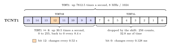
Figure 50: Timer 1’s count as a set of slower counters. With the clock divided by 1024 the whole of TCNT1 goes up 7812.5 times a second. Each bit changes half as often as the one to its right, so bit 8 changes once every 256 counts, and the top byte, TCNT1 >> 8, is a counter of its own that goes up 30.5 times a second and wraps every 8.4 s. Bit 12, shaded, changes every 0.52 s on its own.
In code, the timer only needs its prescaler, and it runs freely in normal mode:
TCCR1A = 0;
TCCR1B = (1<<CS12) | (1<<CS10);              /* normal mode, clock / 1024 */

uint8_t start = TCNT1 >> 8;
while ((uint8_t)((TCNT1 >> 8) - start) < 61) { }   /* 61 x 32.8 ms = 2.0 s */
The subtraction is done in 8 bits on purpose. When the count wraps from 255 to 0, now - start still comes out as the number of steps in between, so long as fewer than 256 have passed. week10-lab-adc-and-spi paces all its programs this way.
Modes: what happens at TOP
The waveform generation mode bits — WGM02:0 for the 8-bit timers, WGM13:0 for timer 1, split across TCCRnA and TCCRnB — decide what the count does when it reaches its TOP, and what TOP is:
| Mode | TOP | At TOP | Timer 0 WGM02:0 |
Timer 1 WGM13:0 |
|---|---|---|---|---|
| Normal | 0xFF / 0xFFFF | wrap to 0, set TOVn |
000 (0) |
0000 (0) |
| CTC — clear timer on compare match | OCRnA |
clear to 0, set OCFnA |
010 (2) |
0100 (4) |
| Fast PWM, fixed top | 0xFF | wrap to 0 | 011 (3) |
0101–0111 (8-, 9-, 10-bit) |
| Fast PWM, top in a register | OCRnA |
wrap to 0 | 111 (7) |
1111 (15; 1110 uses ICR1) |
| Phase correct PWM | 0xFF or OCRnA |
count back down | 001 (1), 101 (5) |
0001–0011, 1011 |
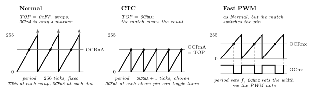
Figure 51: The three modes this course uses, as the count against time. In normal mode the counter runs to its full range and wraps; a compare value is just a marker it passes on the way, and the period is fixed at \(2^{8}\) or \(2^{16}\) ticks. In CTC mode reaching OCRnA clears the counter, so the compare value is the period and can be set to anything — the mode for producing an event at a chosen rate. In fast PWM the counter runs as in normal mode (or, in the register-top variant, as in CTC) while the compare match switches a pin partway through each sweep: the period sets the frequency and the compare value sets the pulse width. The same counter and the same compare registers produce all three; the mode bits only change what the top of the count means.
Normal is the mode after reset and the mode for a free-running count: read TCNTn to see how much time has passed, or let it overflow and take the overflow as the tick. CTC is the mode for an event every \(X\) ticks: the period is OCRnA + 1 exactly, with no wasted counts, and the count never exceeds the compare value. Both PWM modes are in pulse-width-modulation.
Output compare: what a match does to the pin
Each compare unit has two compare output mode bits, COMnx1:0 in TCCRnA, that decide what happens to the OCnx pin when TCNTn equals OCRnx. In the non-PWM modes (Normal, CTC):
COMnx1 |
COMnx0 |
On compare match |
|---|---|---|
| 0 | 0 | normal port operation — the pin belongs to the port, timer disconnected |
| 0 | 1 | toggle OCnx |
| 1 | 0 | clear OCnx — set the output low |
| 1 | 1 | set OCnx — set the output high |
Toggle is the useful one for a square wave: a CTC count that toggles the pin on every match produces a waveform whose frequency is half the match frequency, since it takes two matches for one full cycle. In the PWM modes the same bits select non-inverting (10) or inverting (11) output, and 01 becomes toggle OCnA on match only in the register-top mode — see pulse-width-modulation.
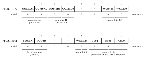
Figure 52: The two control registers of timer/counter 0, bit by bit, in the datasheet’s three-row form. The compare output mode fields sit at the top of TCCR0A, one two-bit field per compare unit; the three waveform generation mode bits are split, two at the bottom of TCCR0A and one in the middle of TCCR0B; the clock select field is the bottom three bits of TCCR0B. The two force-output-compare bits are for tests and are left alone. Every bit resets to 0, which decodes as normal mode, pins disconnected, timer stopped — so a timer does nothing until a program writes both registers. Timer 2’s registers have the same layout; timer 1 spreads the same fields over three registers with a fourth WGM bit.
Setting them from C uses the bit names from the header as shift counts, the idiom of bit-masking: TCCR1B = (1<<WGM12) | (1<<CS11) | (1<<CS10); selects CTC mode with clock ÷ 64 on timer 1, and TCCR0A = (1<<COM0A0); makes OC0A toggle on match. Write the whole register rather than |= when setting a timer up, so that nothing left over from before survives.
The master formula
Every timing question reduces to one relation between the clock, the prescaler and the top of the count:
\[f_{event} = \frac{f_{clk\_I/O}}{N \cdot (TOP + 1)}\]
- \(f_{clk\_I/O}\) is the device clock — 8 MHz on the ATmega324A boards.
- \(N\) is the prescaler: 1, 8, 64, 256 or 1024.
- \(TOP\) is the highest value the count reaches before it restarts: 255 or 65535 in normal mode and the fixed PWM modes, the value in
OCRnAin CTC mode and the register-top PWM modes. The \(+1\) is because the count from 0 to \(TOP\) takes \(TOP + 1\) ticks. - \(f_{event}\) is how often the count restarts — which is how often whatever is tied to the restart happens.
What the event is depends on what is hung off the timer:
| Tied to the restart | \(f_{event}\) is | Note |
|---|---|---|
| a pin set to toggle on match | the toggle rate | the resulting square wave has frequency \(f_{event}/2\) — one cycle needs a rise and a fall |
| a PWM output | the pulse rate | one falling edge per period in non-inverting mode, one rising edge in inverting |
| an interrupt | how often the handler runs | avr-interrupts |
Worked example. Toggle a pin 8 times a second (a 4 Hz square wave) from timer 1: \(f_{event} = 8\), so \(N \cdot (TOP + 1) = 8\,000\,000 / 8 = 1\,000\,000\):
| \(N\) | \(TOP + 1\) | \(TOP\) | Usable? |
|---|---|---|---|
| 1 | 1 000 000 | 999 999 | no — exceeds 65535 |
| 8 | 125 000 | 124 999 | no — exceeds 65535 |
| 64 | 15 625 | 15 624 | yes — integer and fits |
| 256 | 3 906.25 | — | no — not an integer |
| 1024 | 976.5625 | — | no — not an integer |
So OCR1A = 15624 in CTC mode with CS12:0 = 011. The recipe is always the same: fix \(f_{event}\), try each \(N\), keep the one that gives an integer \(TOP\) that fits the timer’s width; if none does exactly, take the nearest and accept the error. Lab 12 works this example in full (week8-lab-avr-timers).
Reading the flags
A program finds out that a match or overflow happened either by polling TIFRn, below, or by enabling the matching bit in TIMSKn so that the event raises an interrupt (avr-interrupts). When an interrupt is taken, the hardware clears the flag itself; a polling program must clear it. Two things about those flags are unlike anything on a port:
- A flag is cleared by writing a 1 to it, not a 0:
TIFR1 = (1<<OCF1A);clears the compare-A flag and leaves the others alone (writing 0 to a bit does nothing). It is the one place where|=is a mistake, since it would clear every flag that happened to be set. - The flag is set by the hardware whether or not the pin is connected or an interrupt is enabled, so a CTC timer with
COM = 00still raisesOCFnAevery period — a free periodic tick for a program that just needs to wait.
/* wait one period of a running CTC timer 1 */
while (!(TIFR1 & (1<<OCF1A))) { }   /* spin until the flag is set */
TIFR1 = (1<<OCF1A);                  /* clear it for next time */
See also
- pulse-width-modulation — the PWM modes, duty cycle and their formulas
- week8-lab-avr-timers — Lab 12:
TCCR1A/B/Cbit by bit, the master formula worked, two programs - week9-lab-avr-pwm — Lab 13: PWM on timers 0 and 1 · week9-lab-avr-interrupts — Lab 14: a 10 ms tick from timer 1
- week10-lab-adc-and-spi — Lab 16: a free-running timer 1 read as
TCNT1 >> 8to pace four programs - software-timers — one timer serving every timing job in a program
- avr-io-ports — I/O registers, the two address spaces,
in/outversuslds/sts - c-preprocessor-and-avr-headers — why
TCCR0AandOCR1Bcan be assigned to · bit-masking —(1<<CS11) - counters — the digital-logic counter this is built from · avr-architecture — the block diagram
- 2026-09-14-flow-of-control — Lecture 15 · 2026-09-17-pulse-width-modulation — Lecture 16
The AVR USART
The ATmega324A’s serial port: the pins, the five registers a program uses, how to set the baud rate, how to send and receive a byte, and the three interrupts. What a UART frame is, and what baud rate and parity mean, are in serial-communication. First met in 2026-09-24-serial-io. The datasheet covers the USART on pages 175 to 201.
What it is
A USART is a Universal Synchronous and Asynchronous Receiver/Transmitter. The course uses it in its asynchronous mode, as a UART: frames with start and stop bits, no clock wire.
The ATmega324A has two, USART0 and USART1. USART0’s pins are on port D:
| Pin | Name | Direction |
|---|---|---|
| PD0 | RXD0 |
receive: data coming in |
| PD1 | TXD0 |
transmit: data going out |
Turning the receiver or transmitter on takes its pin away from the port, in the same way a timer takes over its output-compare pin (avr-timers-and-counters).
The registers
| Register | Holds |
|---|---|
UDR0 |
the data: write a byte to send it, read to collect a received byte |
UCSR0A |
status flags, and two mode bits |
UCSR0B |
interrupt enables, receiver and transmitter enables |
UCSR0C |
the frame format |
UBRR0 (UBRR0H, UBRR0L) |
the baud rate |
The 0 in each name is the USART number. The datasheet writes the names with an n in its place, as in UDRn.
The data register
UDR0 is two registers at one address. A write goes to the transmit buffer. A read comes from the receive buffer. So
UDR0 = 'A';        /* send the letter A            */
c = UDR0;          /* collect whatever has arrived */
and reading UDR0 never returns the value that was written to it.
Behind each buffer is a shift register (shift-registers). A byte written to UDR0 waits there until the transmit shift register is free, is copied across, and is shifted out of TXD0 bit by bit, with the start bit, any parity bit and the stop bits added. On the way in, bits from RXD0 are shifted into the receive shift register, and the finished byte is copied to the receive buffer.
That makes the transmitter two bytes deep: one byte going out and one waiting behind it. It is why there are two separate “finished” conditions, below.
Control and status registers
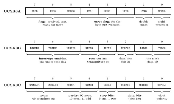
Figure 53: The three control and status registers of USART0, with their bits grouped by what they do. The top three bits of UCSR0A are the flags for the three serial events, and the top three bits of UCSR0B, directly beneath, are the interrupt enables for the same three events in the same order. UCSR0B also switches the receiver and transmitter on. UCSR0C sets the frame format. The number of data bits is the one setting split across two registers: UCSZ02 is in UCSR0B and UCSZ01:00 are in UCSR0C.
UCSR0A: what has happened
| Bit | Name | Set when | Cleared by |
|---|---|---|---|
| 7 | RXC0 |
receive complete: a byte has arrived and has not been read | reading UDR0 |
| 6 | TXC0 |
transmit complete: a frame has been sent and nothing is waiting | its interrupt running, or writing a 1 to it |
| 5 | UDRE0 |
data register empty: UDR0 can take another byte |
writing UDR0 |
| 4 | FE0 |
frame error: the stop bit of the received frame was 0 | the next read of UDR0 |
| 3 | DOR0 |
data overrun: a byte arrived with no room left for it and was lost | the next read of UDR0 |
| 2 | UPE0 |
parity error in the received frame | the next read of UDR0 |
| 1 | U2X0 |
(a setting) 1 doubles the speed: 8 samples per bit, not 16 | |
| 0 | MPCM0 |
(a setting) multi-processor mode, not used here |
After reset UDRE0 is 1, because the transmit buffer starts empty, and every other bit is 0. The three error flags describe the byte currently waiting in UDR0, so they must be read before UDR0.
UCSR0B: what is switched on
| Bit | Name | When 1 |
|---|---|---|
| 7 | RXCIE0 |
the receive-complete flag raises an interrupt |
| 6 | TXCIE0 |
the transmit-complete flag raises an interrupt |
| 5 | UDRIE0 |
the data-register-empty flag raises an interrupt |
| 4 | RXEN0 |
the receiver is on, and PD0 belongs to it |
| 3 | TXEN0 |
the transmitter is on, and PD1 belongs to it |
| 2 | UCSZ02 |
top bit of the data-bits setting (1 only for 9 data bits) |
| 1 | RXB80 |
the ninth data bit of a received 9-bit frame |
| 0 | TXB80 |
the ninth data bit to send in a 9-bit frame |
All 0 after reset: the USART does nothing until RXEN0 or TXEN0 is set.
UCSR0C: the frame format
| Bits | Name | Setting |
|---|---|---|
| 7:6 | UMSEL01:00 |
mode. 00 asynchronous, the one used here |
| 5:4 | UPM01:00 |
parity. 00 none, 10 even, 11 odd |
| 3 | USBS0 |
stop bits. 0 one, 1 two |
| 2:1 | UCSZ01:00 |
data bits, with UCSZ02: 000 5, 001 6, 010 7, 011 8, 111 9 |
| 0 | UCPOL0 |
clock polarity, synchronous mode only |
After reset this register holds UCSZ01:00 = 11 and 0 elsewhere, which is 8 data bits, no parity, 1 stop bit. A program that wants 8N1 does not need to write UCSR0C at all.
Setting the baud rate
\[UBRR0 = \frac{f_{OSC}}{16 \cdot BAUD} - 1\]
\(f_{OSC}\) is the clock, 8 MHz. This is the formula for asynchronous normal mode, the one the course uses, in which the receiver takes 16 samples per bit, and that is where the 16 comes from. The \(-1\) is there because the baud-rate generator counts from UBRR0 down to 0, which is \(UBRR0 + 1\) clock cycles per sample. UBRR0 is 12 bits wide, so 0 to 4095.
The result is rarely a whole number. Round it to the nearest, then work out what rate that really gives, \(f_{OSC} / (16 \cdot (UBRR0 + 1))\), and how far off it is.
| Baud rate | \(\dfrac{8\,000\,000}{16 \cdot BAUD} - 1\) | UBRR0 |
Actual rate | Error |
|---|---|---|---|---|
| 2400 | 207.3 | 207 | 2404 | +0.2 % |
| 4800 | 103.2 | 103 | 4808 | +0.2 % |
| 9600 | 51.1 | 51 | 9615 | +0.2 % |
| 14400 | 33.7 | 34 | 14286 | −0.8 % |
| 19200 | 25.0 | 25 | 19231 | +0.2 % |
| 28800 | 16.4 | 16 | 29412 | +2.1 % |
| 38400 | 12.0 | 12 | 38462 | +0.2 % |
| 57600 | 7.7 | 8 | 55556 | −3.5 % |
| 115200 | 3.3 | 3 | 125000 | +8.5 % |
The receiver tolerates an error of a few percent (serial-communication), so the rates up to 38400 are all within about 2 % at 8 MHz and work, with 28800 the closest to the limit. 57600 is marginal and 115200 does not work. The faster the rate, the fewer clock cycles there are per bit and the coarser the choice of rates becomes. The datasheet has the same table on pages 198 to 201.
In C the register is written in one assignment and the compiler handles the two bytes:
UBRR0 = 51; /* 9600 baud at 8 MHz */Sending and receiving, by polling
The smallest complete program: 9600 baud, 8N1, echo every character back.
#include <avr/io.h>

int main(void) {
    uint8_t c;

    UBRR0  = 51;                          /* 9600 baud at 8 MHz              */
    UCSR0B = (1<<RXEN0) | (1<<TXEN0);     /* receiver and transmitter on     */
                                          /* UCSR0C left at reset: 8N1       */
    while (1) {
        while (!(UCSR0A & (1<<RXC0))) {   /* wait for a byte to arrive       */
        }
        c = UDR0;                         /* collect it (this clears RXC0)   */

        while (!(UCSR0A & (1<<UDRE0))) {  /* wait for room in the data reg.  */
        }
        UDR0 = c;                         /* send it back                    */
    }
}
The two rules it follows:
- Before reading
UDR0, checkRXC0. If nothing has arrived there is nothing to read. - Before writing
UDR0, checkUDRE0. A write while the previous byte is still waiting is ignored, so the new byte is never sent.
Both loops are polling (polling-and-interrupts): the processor does nothing else while it waits. At 9600 baud a frame takes about a millisecond to go out, more than 8000 clock cycles.
The three interrupts
| Event | Flag (UCSR0A) |
Enable (UCSR0B) |
Handler |
|---|---|---|---|
| receive complete | RXC0 |
RXCIE0 |
ISR(USART0_RX_vect) |
| data register empty | UDRE0 |
UDRIE0 |
ISR(USART0_UDRE_vect) |
| transmit complete | TXC0 |
TXCIE0 |
ISR(USART0_TX_vect) |
They are vectors 21, 22 and 23, in that order, so receive has the highest priority of the three (avr-interrupts).
Data register empty or transmit complete? They mark different moments, because the transmitter holds two bytes.
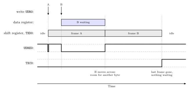
Figure 54: Sending two bytes, A then B, one straight after the other. A moves from the data register into the shift register as soon as it is written, so UDRE0 drops only for an instant and B can be written while A is still on the wire. B then waits in the data register, UDRE0 staying at 0, until A’s stop bit has gone, when it moves across and UDRE0 returns to 1. TXC0 is set only at the very end: the last frame has left and no byte is waiting behind it.
- Use data register empty to keep data flowing: each time it fires, hand over the next byte.
- Use transmit complete when the program needs to know the line has gone quiet, for example before switching the transmitter off.
Receiving by interrupt. The handler runs once per byte, and reading UDR0 is what clears the flag:
#include <avr/io.h>
#include <avr/interrupt.h>

ISR(USART0_RX_vect) {
    uint8_t c = UDR0;                     /* reading clears RXC0             */
    UDR0 = c;                             /* echo (assumes room, see below)  */
}

int main(void) {
    UBRR0  = 51;
    UCSR0B = (1<<RXEN0) | (1<<TXEN0) | (1<<RXCIE0);
    sei();
    while (1) {
        /* free to do anything else */
    }
}
A handler that does not read UDR0 leaves RXC0 set, and it is called again the moment it returns, for ever. The echo here is safe because bytes cannot arrive faster than they can be sent back at the same baud rate.
UDRIE0 needs care. The data register is empty most of the time, so its flag is nearly always set. Enabling the interrupt with nothing to send calls the handler continuously. The pattern is to enable UDRIE0 when there is data queued and have the handler disable it again when the queue runs out.
Common mistakes
- Reading
UDR0to see what was written. Reads and writes go to different registers. - Forgetting
RXEN0orTXEN0. The baud rate and format can be perfect and nothing happens. - Forgetting the \(-1\) in the baud-rate formula, giving 52 for 9600 instead of 51.
- Writing
UDR0without checkingUDRE0, which loses bytes when sending more than one. - Reading
UDR0before the error flags. The flags belong to the byte being read and are gone afterwards. - A receive handler that does not read
UDR0. - Leaving
UDRIE0enabled with nothing to send. - Mismatched settings at the two ends. The symptom is garbled characters, not silence (serial-communication).
See also
- serial-communication — frames, parity, sampling, baud rate against bit rate, RS232
- avr-interrupts — flags, enables, the vector table and writing a handler in C
- polling-and-interrupts — waiting on a flag against being interrupted by it
- avr-timers-and-counters — the master formula the baud-rate formula mirrors
- shift-registers — the heart of the transmitter and the receiver
- bit-masking · c-preprocessor-and-avr-headers —
(1<<RXEN0)and where the names come from - io-board — the USB-serial device at the other end of the wires
- avr-spi — the SPI port, and the USART as an SPI master when
UMSELn1:0=11 - 2026-09-24-serial-io — Lecture 18
Bit Masking
Using a bitwise operation against a constant mask to touch only the bits you care about, leaving the rest alone. See boolean-algebra for the underlying laws and avr-instructions for the instructions used here. The same masks, written from the bit names in the AVR’s header files, are how every I/O register is set up in C: see set, clear and toggle and writing register bits by name.
Sometimes you are interested in only a few bits of a register. A bitwise AND can mask out the bits that are not of interest — and more generally, masking can selectively set, clear, toggle or extract bits.
The reason any of this is possible is that a bitwise instruction is not one eight-bit operation. It is eight independent one-bit operations running in parallel, and the two operands’ bit \(i\) decide result bit \(i\) with no reference to any other column.
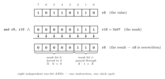
Figure 55: Why a mask works, one column at a time. Two rows of bits, an arrow down out of each column into a result row that overwrites the destination: here and r8, r16 with the mask 0x07, extracting the low three bits. The eight columns never interact — one mask bit decides one result bit, a 1 passing the value’s bit through and a 0 forcing it to zero — and all eight happen at once in a single instruction. Choosing a mask is therefore nothing more than deciding, position by position, which bits to keep.
Read Figure 55 column by column and the technique stops needing to be memorised: since the columns are independent, choosing a mask is just choosing, for each of the eight positions separately, whether that position gets passed through or forced.
The three identities that make it work
Each of AND, OR and XOR has a value that passes a bit through unchanged and a value that forces it. That pairing is the whole technique.
| \(X \cdot 0\) | \(X \cdot 1\) | \(X \cdot X\) | |
|---|---|---|---|
| AND | \(= 0\) | \(= X\) | \(= X\) |
| \(X + 0\) | \(X + 1\) | \(X + X\) | |
|---|---|---|---|
| OR | \(= X\) | \(= 1\) | \(= X\) |
| \(X \oplus 0\) | \(X \oplus 1\) | \(X \oplus X\) | |
|---|---|---|---|
| XOR | \(= X\) | \(= \overline{X}\) | \(= 0\) |
Reading off the pass-through and force columns gives the operation to reach for:
| To do this to the selected bits | Use | Mask bit = 1 on | Mask bit = 0 on |
|---|---|---|---|
| Clear them to 0 | AND |
the bits to keep — \(X \cdot 1 = X\) | the bits to clear — \(X \cdot 0 = 0\) |
| Set them to 1 | OR |
the bits to set — \(X + 1 = 1\) | everything else — \(X + 0 = X\) |
| Toggle them | EOR |
the bits to flip — \(X \oplus 1 = \overline{X}\) | everything else — \(X \oplus 0 = X\) |
| Extract them (others zeroed) | AND |
the bits to keep — \(X \cdot 1 = X\) | the bits to discard — \(X \cdot 0 = 0\) |
Note the asymmetry: AND’s mask is 1 on the bits you keep, whereas OR’s and XOR’s masks are 1 on the bits you act on. Getting that backwards is the usual bug — with AND you write the mask for what survives, with the other two for what changes.
\(X \oplus X = 0\) is the other one worth remembering: XORing a register with itself is the cheapest way to zero it.
In AVR assembly
The masks are ordinary constants, so the bitwise instructions of avr-instructions do the work. On AVR the immediate forms (andi, ori) only reach r16–r31; for a low register, load the mask into a high register and use the two-register form.
Extract the least significant three bits of r7 into r8, other bits of r8 zero.
    mov  r8, r7          ; copy the source
    ldi  r16, 0x07       ; mask 0000 0111 — keep the bottom three
    and  r8, r16         ; everything else forced to 0
Toggle the most significant four bits of r9, other bits unchanged.
    ldi  r16, 0xF0       ; 1111 0000 — flip the top four
    eor  r9, r16         ; bottom four XOR 0, so unchanged
Clear the least significant four bits of r10, other bits unchanged.
    ldi  r16, 0xF0       ; 1 on the bits to KEEP
    and  r10, r16        ; bottom four AND 0 -> 0
Set the most significant four bits of r11 to 1, other bits unchanged.
    ldi  r16, 0xF0       ; 1 on the bits to set
    or   r11, r16        ; bottom four OR 0, so unchanged
Note how 0xF0 appears as the mask in three of these with three different meanings — keep, flip, set — decided entirely by the instruction it is paired with.
In C
The same four operations with C’s bitwise operators (c-operators), which is how every AVR C program touches its ports. The masks are the same; the immediate-register restriction disappears, since the compiler chooses the registers.
| Operation | Operator | Example | Reads as |
|---|---|---|---|
| Clear particular bits | & with 0s on the bits to clear |
var = PINB & 0x0F; |
keep the low nibble, zero the high |
| Test particular bits | & with a 1 on the bit to test |
if (PINB & 0x02) … |
true if bit 1 is set |
| Set particular bits | \| with 1s on the bits to set |
PORTC = PINB \| 0x80; |
force bit 7 to 1 |
| Invert particular bits | ^ with 1s on the bits to flip |
PORTC = PINB ^ 0x0F; |
flip the low nibble |
Write the mask as a shift, not a hex constant: (1<<5) says bit 5 where 0x20 has to be decoded, and the header files name every register bit as a bit number for exactly this use (c-preprocessor-and-avr-headers):
DDRB  = (1<<5);                 /* bit 5 output, every other bit input: REPLACES the register */
DDRB |= (1<<4) | (1<<3);        /* bits 3 and 4 output, the rest unchanged: read-modify-write */
DDRB &= ~(1<<3);                /* bit 3 back to input, the rest unchanged                    */
PORTC ^= (1<<0);                /* toggle bit 0                                              */
TCCR1B = (1<<WGM12) | (1<<CS11) | (1<<CS10);   /* named bits, ORed into one value            */
The difference between the first two lines is the one that bites: = writes the whole register and silently sets the other seven bits to 0, |= ORs into what is already there. In assembly the second line is three instructions — in, ori, out — and the C compiler emits exactly those (week8-lab-avr-c-programming). For a single-bit clear the mask is the complement of the set mask, ~(1<<n), which is why clear bit 3 is &= ~(1<<3) and not &= (1<<3).
The test idiom needs no comparison. PINB & 0x02 is 0x02 when bit 1 is set and 0 when it is not, and C treats any non-zero value as true (c-control-flow) — so if (PINB & 0x02) is right and if ((PINB & 0x02) == 1) is always false, because the masked value is 2, never 1.
Set, clear and toggle on an I/O register
Changing one bit of an I/O register, and only that bit, is one of three lines. Each reads the register, combines it with a one-bit mask and writes it back:
| To | Write | The mask | Why the other bits survive |
|---|---|---|---|
| set bit n | REG \|= (1<<n); |
a 1 on bit n | \(X + 0 = X\) |
| clear bit n | REG &= ~(1<<n); |
a 0 on bit n, 1s elsewhere | \(X \cdot 1 = X\) |
| toggle bit n | REG ^= (1<<n); |
a 1 on bit n | \(X \oplus 0 = X\) |
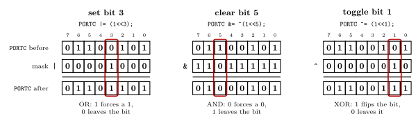
Figure 56: Set, clear and toggle on one register byte. Each panel starts from the same value of PORTC, 0110 0101, and changes one bit, outlined, with a single read-modify-write. The mask is a 1 shifted to the bit’s position, complemented for a clear. In every other column the mask holds the value that leaves a bit alone: 0 for OR and XOR, 1 for AND. Set gives 0110 1101, clear gives 0100 0101 and toggle gives 0110 0111, and each time the other seven bits are untouched.
Toggle is not enable. TIMSK2 ^= (1<<OCIE2A); turns the timer 2 compare A interrupt on only if it was off, and a second run turns it off again. To enable whatever the bit was before, set it with |=; to disable, clear it with &= ~. Toggling is for things meant to alternate, like an LED blinking.
The register has to be one that stores what is written. PORTx and DDRx do. PINx does not: it reads the pins, and on the ATmega324A a 1 written to one of its bits toggles the matching PORTx bit, so a read-modify-write on PINx changes the wrong bits (avr-io-ports).
Writing register bits by name
When setting or clearing bits of an I/O register, be explicit about which bits. Three ways to write the same value, from worst to best:
TCCR1B = 10;                          /* poor:   a number                    */
TCCR1B = 0x0A;                        /* better: the pattern, 0000 1010      */
TCCR1B = (1<<WGM12) | (1<<CS11);      /* best:   the bits, by name           */
WGM12 is bit 3 of TCCR1B and CS11 is bit 1, so all three are 0000 1010. Only the last says which bits, so a reader can check them against the datasheet without decoding anything: CTC mode, clock divided by 8 (avr-timers-and-counters). It costs nothing, either. The compiler works out (1<<WGM12) | (1<<CS11) while compiling, and all three lines become the same instructions.
The names are bit numbers. The device header that <avr/io.h> includes defines every bit name as the bit’s position in its register:
#define WGM02 3A name is not a mask; 1<< makes it one (c-preprocessor-and-avr-headers). The names are the datasheet’s, and the datasheet has errors in places, so the I/O register summary at the back is the one to check a name against.
Assembly uses the same names. In ldi r16, (1<<WGM02)|(1<<CS01) the assembler works out the constant, 0x0A, and the instruction stored is ldi r16, 0x0A.
A name belongs to one register. WGM12 and WGM02 are both 3, so (1<<WGM12) written into TCCR0B sets WGM02, and the compiler cannot notice, because all it sees is the number 3. Pair each name with the register whose datasheet entry defines it. The same byte 0x0A is CTC mode in TCCR1B and a reserved mode in TCCR0B (2026-10-05-more-io).
Masking sets the status flags too
Status register flags will be set also — a mask operation is a real ALU operation, not a free one. AND, OR and EOR all clear V and set N and Z from the result (C is untouched); see avr-architecture.
That side effect is often the actual point. andi r16, 0x01 keeps only bit 0, so:
\[Z = 1 \iff \text{bit 0 of } \texttt{r16} \text{ is } 0 \iff \texttt{r16} \text{ is even}\]
which makes a single masked AND an even/odd test. Any single-bit mask turns the Z flag into a test of that one bit — and tst rd, which is just and rd, rd, is the degenerate case that tests the whole register against zero.
Common mistakes
&= (1<<n)to clear bit n. That keeps bit n and clears the other seven. A clear’s mask is the complement,~(1<<n).=where|=was meant.DDRB = (1<<5)makes PB5 an output and every other pin of port B an input.- A bit name without the shift.
TCCR1B |= WGM12;ORs in the number 3,0000 0011, which setsCS11andCS10, clock divided by 64, and leavesWGM12alone. - A bit name in the wrong register.
(1<<WGM12)inTCCR0BsetsWGM02. ^=to enable. A toggle enables only from off; run twice, it disables.- A read-modify-write on
PINx. WritingPINxtoggles outputs, so it cannot clear or set a bit. - Getting AND’s mask backwards. With AND the 1s mark the bits to keep; with OR and XOR they mark the bits to change.
if ((x & mask) == 1). The masked value is the mask’s own value, so the test is false unless the mask is bit 0. Test for non-zero.
See also
- boolean-algebra · avr-instructions · avr-architecture
- avr-io-ports — one bit of a port in C and assembly, and why
PINxis different - avr-timers-and-counters — the
TCCRnBfields named in the examples - 2026-10-05-more-io — Lecture 19: poor, better and best,
TIMSK2toggled - week5-lab-avr-assembly-one — Lab 9, where these snippets are the exercise
- week8-lab-avr-c-programming — Lab 11, the same operations in C · c-operators · c-preprocessor-and-avr-headers
C Language Basics
What a C program is made of: the shape of a program, variables and their types, functions, and constants. Operators are in c-operators, the if/while/for statements in c-control-flow, arrays and pointers in c-pointers-and-arrays, and the preprocessor in c-preprocessor-and-avr-headers. First met in 2026-09-07-introduction-to-embedded-c-programming.
Where C sits
C is the top layer of the course’s three blocks — high-level programming over low-level programming over digital logic design — and the course’s C is embedded C for the ATmega324A, the same chip the assembly targeted. The difference from assembly is one extra tool. An assembler turns each line into exactly one instruction; a compiler turns each C statement into however many instructions it needs, chooses the registers, and hands the result to the assembler. The chain from C statement down to control unit is drawn in 2026-09-07-introduction-to-embedded-c-programming, and the steps after the compiler, object files and the linker, are in compilation-and-linking.
What is expected: write small C programs and functions from scratch, understand the meaning of C programs, and write or modify C programs — practised in Labs 11–16, which all use C.
The shape of a program
- There must be a function called
main; it is executed when the program starts. - Blocks of code are enclosed by braces
{ }. - Statements end with a semicolon
;. - C is case sensitive —
variableandVariableare different names. - Comments are
/* … */(any length, may span lines) or//to the end of the line.
/* the smallest useful embedded program: */
#include <avr/io.h>

int main(void) {
    DDRA = 0xFF;        /* a statement */
    while(1) {          /* a block */
        PORTA = 0x55;
    }
}
On the AVR main never returns — there is no operating system to return to — so every program ends in an infinite loop (c-control-flow). #include is the preprocessor’s (c-preprocessor-and-avr-headers).
Variables and types
Declaration: type-name variable-name, variable-name …;
A declaration reserves room in data memory (memory-models) and gives it a name and a type. The type decides two things: how many cells the variable takes, and how the bits are read — the signed/unsigned question of binary-number-representations, now answered once at the declaration instead of instruction by instruction.
| Declaration | Size | Range | |
|---|---|---|---|
char c; |
1 byte | −128 … 127 | two’s complement |
unsigned char x; |
1 byte | 0 … 255 | |
int day; |
machine dependent — 16 bits on the AVR | −32768 … 32767 | two’s complement |
unsigned int count; |
as int |
0 … 65535 on the AVR | |
float |
32 bits | about \(\pm 3.4 \times 10^{38}\), 7 digits | IEEE single precision; no AVR hardware — done in software |
double |
64 bits in general; 32 on avr-gcc | likewise |
On avr-gcc float and double are interchangeable: both are 32 bits (below).
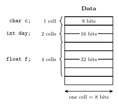
Figure 57: What three declarations reserve in the AVR’s 8-bit data memory, drawn as a memory map. char is one cell. int is two, because int is 16 bits on the AVR — which is why a pointer to an int steps by two in the pointers note. float is four, because single precision is 32 bits. The compiler decides the actual addresses; the addresses here are schematic and the order is arbitrary.
Three consequences worth carrying around:
charis an integer. It is exactly the 8-bit two’s complement byte of the hardware block; the name only promises it can hold a character code. Arithmetic on it is byte arithmetic, and'A' + 1is'B'because'A'is 65.intis not one size. Write code that assumes 16 bits and it breaks on a desktop; assume 32 and it breaks on the AVR. The AVR headers provideuint8_t,int16_tand friends — types with the width in the name — and the course’s example program usesuint8_tfor exactly this reason.- Nothing is checked. Storing 300 in an
unsigned chardoes not fail; it stores 300 mod 256, i.e. 44. (For a signedcharthe C standard leaves the result implementation-defined; gcc also gives 44.) The type is a reading rule, not a guard.
Booleans. There is no boolean type in the course’s C. Any value can be treated as a boolean: zero means false, non-zero means true. This is what lets if(a) mean if(a != 0) (c-control-flow).
Functions
return-type function-name (arg-decl)
{
    variable-declarations;
    …
    statements;
}| Part | Meaning | Example |
|---|---|---|
return-type |
what type is returned, or void for nothing |
int, void |
function-name |
the name; main for the entry point |
average |
arg-decl |
argument (parameter) declarations, comma-separated, each with its type | int a, float b |
variable-declarations |
variables used only within the function | int avge; |
statements |
the code which actually does stuff |
An example:
/*
  Return the average of two integers
  (result will be rounded towards 0)
*/
int average(int a, int b) {
    int avge;

    avge = (a+b)/2;

    return avge;
}
avge = (a+b)/2;is a statement built from expressions —(a+b), then(a+b)/2, then the assignment; the outermost expression plus its semicolon is the statement.return avge;hands the value back and ends the function.avgeis local: it exists only whileaverageis running. Nothing outside can name it.- Integer division truncates toward zero.
average(1, 2)computes3/2and returns1; the.5never exists. The comment says rounded towards 0, and that is the whole of C’s rule for/on integers —-3/2is-1, not-2.
A function with void in front returns nothing and is called for its effect. int main(void) is a function whose argument list is explicitly empty.
Where a variable lives
Where a declaration is written decides where the compiler stores the variable and how long it exists.
| Declaration | Kind | Stored | Exists |
|---|---|---|---|
outside every function: int count; |
global | at a fixed address in data memory, from 0x0100 up |
for the whole run |
inside a function: int avge; |
local | in the call’s stack frame | only while that call runs |
inside a function: static int calls; |
static local |
with the globals, at a fixed address | for the whole run, keeping its value between calls |
outside every function: static int a; |
static global |
like any global | for the whole run; the name is private to its file |
So avge in average above is made fresh on every call and is gone at the return, and a local that is never assigned starts out holding whatever was left on the stack. A static local is the way to have a function remember something from one call to the next. Memory obtained from malloc() comes from a third place, the heap, which grows from above the globals toward the stack. The full picture is in compilation-and-linking, and the frame itself is in procedures-and-the-stack.
Constants
Character constants
Single quotes: 'a', 'b', '1'. A character constant is a number — its ASCII code — so '1' is 49, not 1.
| Range | Codes |
|---|---|
'A' … 'Z' |
65 … 90 |
'a' … 'z' |
97 … 122 |
'0' … '9' |
48 … 57 |
Which makes c - '0' the digit value of a digit character, and c + ('a' - 'A') the lower-case of an upper-case letter — both plain integer arithmetic.
Special characters are backslash escaped:
'\n' |
newline |
'\'' |
single quote |
'\t' |
tab |
'\\' |
backslash |
String constants
Double quotes, escapes allowed inside: "abc \n \" hello\t". A string is an array of char (c-pointers-and-arrays).
Integer constants
| Base | Written | Examples |
|---|---|---|
| Decimal | as usual | 3, -27, 65535, +5 |
| Hexadecimal | leading 0x |
0x5F, 0xFFFF, 0xDEADBEEF |
| Octal | leading 0 |
0377 = 255 |
The octal rule is a trap: a leading zero changes the base. 010 is eight. Do not zero-pad a decimal constant.
Hexadecimal is the natural notation for anything that is really a bit pattern — port values, masks — because each digit is exactly one nibble (binary-number-representations). 0xFF is 11111111 at a glance; 255 is not.
Floating point constants
Include a decimal point and/or an e exponent: 3.1416, -7., 6.02e23, -5.2e-2. 7 is an integer; 7. is floating point. The type of a constant is decided by how it is written, and it decides what arithmetic happens: 7/2 is 3, 7./2 is 3.5.
Floating point on the AVR
float and double are usually IEEE single and double precision, but the C standard only asks for minimums: about 6 significant decimal digits for float and 10 for double, both up to \(10^{37}\). avr-gcc makes double the same 32-bit single precision as float, which gives about 7 digits and so falls short of what the standard asks of double. Code written for a desktop that relies on double quietly loses half its digits on the AVR.
The AVR also has no floating-point hardware: its only hardware data type is the 8-bit integer (instruction-set-architecture). Every float add, multiply or conversion is a call into a software library, hundreds of instructions with branches where an integer operation takes a few. So where integer arithmetic can give the same result, use it:
PORTB = PINA / 3;        /* integer: a handful of instructions, no branches */
PORTB = PINA * 0.334f;   /* float: the same results, 300+ instructions      */
Scaling to whole units (millivolts, tenths of a degree) or using fixed-point-numbers keeps the fractions without the floats. The formats themselves, and why 0.1 cannot be stored exactly, are in floating-point-numbers.
See also
- c-operators · c-control-flow · c-pointers-and-arrays · c-preprocessor-and-avr-headers
- binary-number-representations — the signed/unsigned readings behind
charandunsigned char - floating-point-numbers — what
floatanddoublehold, and their cost on the AVR · fixed-point-numbers — fractions in integer arithmetic - memory-models — the 8-bit data cells a declaration reserves
- instruction-set-architecture — the data types the AVR supports in hardware, and the ones it does not
- compilation-and-linking — how the compiler maps globals, locals and statics to memory, and what happens after compiling · procedures-and-the-stack — the stack frame a local lives in
- 2026-09-07-introduction-to-embedded-c-programming — Lecture 13 · 2026-10-15-compilation-and-linking — Lecture 22 · 2026-10-19-floating-point-numbers — Lecture 23
C Preprocessor and AVR Headers
The preprocessor — #include and #define — and the three lines of avr/io.h that let DDRA = 0xFF; be written as if a hardware register were a variable. First met in 2026-09-10-more-c-programming-on-the-avr; the port registers themselves are in avr-io-ports.
What the preprocessor is
C programs are first parsed by a preprocessor, which replaces preprocessor directives with substitute text. Only then does the compiler see the program. Directives start with #:
| Directive | Does |
|---|---|
#include … |
paste in a file |
#define … |
define a macro — a textual substitution |
#if, #ifdef, #else, #undef, … |
conditional inclusion, un-definition, and others |
The preprocessor does not know C. It edits text. Whatever it produces is what the compiler compiles, and every surprise in this note comes from forgetting that.
#include
| Form | Kind of header | Looks in |
|---|---|---|
#include <filename.h> |
system | the system include directories — where avr/io.h and stdio.h live |
#include "filename.h" |
user-defined | your own project directory first |
The directive is replaced by the whole contents of the named file, at that point. After preprocessing there is one file, with the header pasted in at the top.
Header files
Header (.h) files are used for common macros, function prototypes etc — the C counterpart of m324Adef.inc in assembly (avr-io-ports).
stdio.h— prototypes ofprintf()etc. The AVR has a simplified version (no files);printf()only works if you say where the characters go, e.g. a serial port.avr/io.h— defines the AVR’s useful constants and functions/macros. Definitions depend on the actual device targeted: it reads which chip is being compiled for and pulls in that chip’s register map, soDDRAmeans the right address for the ATmega324A and a different one for another part. It also suppliesuint8_tand the other fixed-width types.
Every program in the course starts with #include <avr/io.h>.
Headers against libraries
A header file is not the library. A header
- defines useful preprocessor macros,
- declares the functions that are in the library, as function prototypes, and
- declares variables that are available externally, with
extern.
The library is the collection of object files that implements the functions (compilation-and-linking).
A prototype such as int printf(const char *fmt, ...); tells the compiler the name, the argument types and the return type. That is enough for the compiler to check a call and generate it. There is no code in it, so in main.o the call to printf is left as an external reference. The code is in the library, an object file printf.o inside it, and the linker joins it on and fills in the address. An extern declaration does the same for a variable: extern int count; says that count exists somewhere else and reserves nothing.
So the header goes to the compiler, through the preprocessor, and the library goes to the linker. The two kinds of mistake show up at different steps:
| Missing | Shows up when | Typical message |
|---|---|---|
the #include |
compiling | implicit declaration of function printf |
the library, or the .c file that defines the function |
linking | undefined reference to printf |
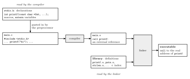
Figure 58: Where a header and a library each come into play, for a program that calls printf. The header holds only declarations. The preprocessor pastes it into main.c so that the compiler can check and generate the call, and in main.o that call is still an external reference. The library holds the definitions, as already compiled object files with an index. The linker finds printf.o through the index, links it in, and fills in the call. The header is used by the compiler and the library by the linker.
#define — macros
Macros are textual substitutions.
| Macro | Effect |
|---|---|
#define pi 3.1415 |
every later pi becomes 3.1415 — A = pi * r²; becomes A = 3.1415 * r²; (the superscript is shorthand; in real C the square would be r * r) |
#define EVER ;; |
for(EVER) becomes for(;;), an infinite loop |
#define sum(a,b) (a+b) |
a macro with parameters: sum(x, 2) becomes (x+2) |
A macro with parameters looks like a function call and is not one: no call happens, the arguments are pasted into the body as text, and the result is compiled in place.
The SQUARE trap
Given
#define SQUARE(x) (x*x), what isSQUARE(1+2)?
5, not 9. Paste the text: (1+2*1+2). Multiplication binds tighter than addition, so it is \(1 + 2 + 2\). The argument was never evaluated first, because there is no function to evaluate it.
The fix is parentheses around every parameter, and around the whole body:
#define SQUARE(x) ((x)*(x)) /* SQUARE(1+2) -> ((1+2)*(1+2)) = 9 */The outer pair matters as much as the inner: without it, 1 / SQUARE(a) becomes 1 / (a)*(a), which is \(a\), not \(1/a^2\). Write every macro this way. The AVR headers below do — note the brackets around (mem_addr) and (io_addr).
A second pitfall: an argument with a side effect is pasted as many times as the parameter appears. SQUARE(i++) becomes ((i++)*(i++)) and increments i twice.
The avr/io.h register macros
The definitions behind the port names, from avr/io.h and the device header it includes:
#define _MMIO_BYTE(mem_addr) \
                (*(volatile uint8_t *)(mem_addr))
#define _SFR_IO8(io_addr) \
                _MMIO_BYTE((io_addr) + 0x20)

/* Input Pins, Port A */
#define PINA      _SFR_IO8(0x00)

/* Data Direction Register, Port A */
#define DDRA      _SFR_IO8(0x01)

/* Data Register, Port A */
#define PORTA _SFR_IO8(0x02)(\ at the end of a line continues a directive onto the next line.)
Upshot: I/O register names can be used as variables.
DDRA = 0xFF;
PORTA = PINC | 0xF0;
Unrolling DDRA
| Step | Text |
|---|---|
| as written | DDRA = 0xFF; |
#define DDRA |
_SFR_IO8(0x01) = 0xFF; |
#define _SFR_IO8 |
_MMIO_BYTE((0x01) + 0x20) = 0xFF; |
#define _MMIO_BYTE |
(*(volatile uint8_t *)((0x01) + 0x20)) = 0xFF; |
Reading the final line from the inside out:
(0x01) + 0x20is0x21— a number.(volatile uint8_t *)casts it: treat this number as the address of an 8-bit unsigned byte. Now it is a pointer (c-pointers-and-arrays).- The leading
*dereferences it: the byte at that address. = 0xFFstores into that byte.
So DDRA = 0xFF; is a store to data address 0x21, and x = PINC; is a load from data address 0x26. There is no variable called DDRA anywhere; the name dissolves before the compiler sees it.
Why + 0x20
The AVR’s 64 I/O registers have two addresses each (avr-io-ports): an I/O-space number 0–63, which is what in and out use, and a data-space address 0x20 higher, where lds/sts — and any C pointer — find the same register. DDRA is I/O 0x01 and data 0x21. The macro takes the I/O number the datasheet lists and adds the offset, because a C pointer can only name data-space addresses. (The compiler, seeing a constant address in the I/O range, will usually emit in/out anyway.)
Why volatile
volatile tells the compiler the value at this address can change without the program changing it, and that every read and write matters. Without it the compiler is entitled to assume that a byte it wrote a moment ago still holds what it wrote, and that two reads with nothing between them give the same answer — both false for a port: PINC changes whenever the pins do, and PORTA is written for its effect on the pins, not to be read back. volatile forbids the optimisations that would break that. It is the one piece of the macro that is about hardware rather than addressing.
The same keyword belongs on any ordinary variable that an interrupt handler writes. To the code in main, a handler’s write is as invisible as a pin changing, and for the same reason: nothing in main’s own flow of control explains it. See avr-interrupts.
Naming bits
The headers also define bit numbers for every flag and pin — for example FLAG_NAME == 5 — so a mask is written from a name rather than a constant:
1 << FLAG_NAME              /* 00100000 when FLAG_NAME is 5 */
PORTA |= (1 << 5);          /* set one bit                   */
PORTA &= ~(1 << 5);         /* clear one bit                 */
The shift and the |=/&= shorthands are in c-operators; the mask patterns are in bit-masking. FLAG_NAME is a placeholder name; the actual names for the ATmega324A’s pins and flags come from the device header, as #define WGM02 3 does in 2026-10-05-more-io.
See also
- avr-io-ports — the port registers, and the I/O-space versus data-space address columns
- c-pointers-and-arrays — what
*(uint8_t *)addrmeans - c-operators —
1 << n,|=,&= - bit-masking · memory-models
- avr-interrupts —
volatileon variables shared with an interrupt handler - compilation-and-linking — what happens after the preprocessor: object files, libraries and the linker · 2026-10-15-compilation-and-linking — Lecture 22
- 2026-09-10-more-c-programming-on-the-avr — Lecture 14
The I/O Board
The I/O board in the lab kit carries the input and output devices you wire your breadboard circuits to, for experimenting with simple digital circuits. It plugs directly onto the breadboard, and adds a logic probe for debugging and a UART serial interface for talking to other devices.
It is powered from a single USB connection and has current-sense circuitry that detects short circuits and protects your designs.
Pin numbers for every device are in device-pinouts; the kit itself is loaned out in week3-lab-logisim-and-flip-flops. Two more parts of the kit that are used alongside the board, the joystick and the LED matrix, are described at the end.
What’s on it
| 1. USB connector | 2. Power LED | 3. Power switch | 4. 7-segment display |
| 5. Switches | 6. LEDs | 7. Buttons | 8. UART transmit/receive LEDs |
| 9. Logic probe indicator LEDs | 10. Fault LED | 11. VCC / GND headers | 12. I/O device headers |
| 13. Auxiliary power connector | 14. High current mode jumper |
Items 13 and 14 are the auxiliary power connector and the high-current-mode jumper. The one extra power connection the labs use is connector J1, which powers the LED matrix in Lab 16 (below).
The board at a glance
The board is a C shape: a left-hand spine carrying the USB connector, the power switch, the two status LEDs and the seven-segment display, plus a top arm and a bottom arm that straddle the breadboard’s central channel. All the I/O devices come out on the two 16-pin headers on the inner edges of those arms, and every device is reached through the column of breadboard holes directly above or below its printed label.
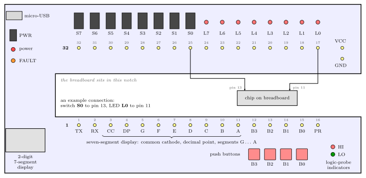
Figure 59: A plan view of the board, not to scale, with the parts on the left spine placed roughly. Each I/O device sits on one pin of one of the two 16-pin headers, and the column of breadboard holes at that pin is how you reach it. The board itself prints only the two end markers, a bold 32 at the left of the top header and a bold 1 at the left of the bottom one. The small numbers at the other pins are their pin numbers, the ones a schematic uses. The connection drawn in the notch is an example: switch S0 to pin 13 of a chip, LED L0 to pin 11.
Two things about the numbering are worth fixing in your head before you wire anything:
- The top header counts down, left to right. Its leftmost pin is 32 and its rightmost is 17, so the switches run
S7…S0and then the LEDsL7…L0as you read left to right. That is the opposite of the reading order you would guess from the pin numbers alone. - The bottom header counts up, left to right, pin 1 to pin 16:
TX RX CC DP G F E D C B A B3 B2 B1 B0 PR. The middle nine of those are the seven-segment display —CCits common cathode,DPits decimal point, andGdown toAits seven segments — which is why nine consecutive pins carry single-letter names.
VCC and GND pads sit at the far right of both arms, which is where the breadboard’s power rails get fed from.
Setup
Insert the board into the breadboard, aligning the downward-facing headers with the right holes.
If aligned correctly, the I/O board should not require excessive force to insert.
Connect a micro-USB cable to the connector at the top-left corner.
DO NOT STORE THE BOARD WITH THE USB CABLE ATTACHED — THIS MAY CAUSE THE USB CONNECTOR TO BREAK OFF!!
The USB connector is the part people break.
Turn the board on by sliding the PWR switch up to ON; the red power LED should light. Then check the orange FAULT LED does not light. If it does, power off immediately.
The fault LED
The board uses a current-limited power switch to protect itself and anything it powers from short circuits. A short lights the orange FAULT LED.
If it’s on: push PWR down to OFF immediately, and check your design for shorts before restoring power.
WARNING! In the case of a short circuit, the current-limiting switch may become extremely hot.
The logic probe
Attach a wire to the column of terminals above the PR label — pin 16, the rightmost pin of the bottom header. Touch the free end to any point in the circuit and the HI / LO LEDs show the logic state there.
As circuits increase in complexity, so does the necessity of having a clear strategy — probing random points in a large circuit rarely reveals the location of errors.
Suggested troubleshooting strategy
- Check the FAULT light is not on, which would indicate a short circuit.
- Probe VCC and GND at every device in your circuit, to confirm each one is actually powered.
- Start at the inputs and move logically through to the outputs. Pen and paper helps: write down the expected state at each point first, then verify it with the probe. A schematic and a truth table are great for this.
The key to any successful debugging strategy is to assume nothing, know what to expect before you begin testing, and have a plan.
Step 2 is the one worth internalising — an unpowered chip looks exactly like a wrong-logic chip until you probe its power pins, and grouped VCC/GND entries on a schematic (see circuit-schematics) make it easy to forget one.
Electrical characteristics
| VCC | 5 V |
| GND | 0 V |
| Logic high | > 3.5 V |
| Logic low | < 1.5 V |
The gap between 1.5 V and 3.5 V is undefined, which is why a floating pin can read as either (week3-lab-logisim-and-flip-flops). What the logic probe shows for a voltage inside that band is not documented.
The joystick
The kit’s two-axis joystick is a small board of its own, made to sit in the breadboard next to the I/O board. Each axis is a potentiometer between its own supply pin and ground, and the stick moves the wiper. So each axis gives a voltage that follows the stick across its travel, from 0 V at one side to 5 V at the other, for the A/D converter to read (analog-to-digital-conversion).
| Pin | What it is | Connect to |
|---|---|---|
| L/R+ | top of the left-right potentiometer | VCC |
| U/D+ | top of the up-down potentiometer | VCC |
| GND ×2 | bottom of both | GND, either one |
| L/R ×2 | x: 0 V with the stick to the left, 5 V to the right | an analog input, either one |
| U/D ×2 | y: 0 V at the bottom, 5 V at the top | an analog input, either one |
- The doubled pins are joined on the board. One wire to each of L/R, U/D and GND is enough.
- The two
+pins are separate. Both have to go to VCC, or one axis has nothing to divide. - Left, right, up and down are the joystick’s own, marked by the X and Y arrows printed on it. Placed at the right-hand end of the breadboard, with room for the microcontroller board and programmer to its left, the X arrow points to the top of the breadboard and the Y arrow to the left.
- A potentiometer’s wiper is a weak source. Anything that draws current from it, an LED for instance, pulls its voltage away from the stick’s position. LEDs make a quick wiring test, but they must come off before the converter is used.
- Keep the black foam that protects the pins when the joystick is put away.
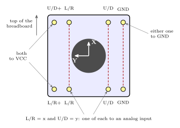
Figure 60: The joystick’s eight pins, seen from above with the board placed as it sits in the breadboard, its X arrow pointing to the top. The pins near each corner come in twos. The dashed lines join the pins that are connected on the board itself: the two L/R pins, the two U/D pins and the two GND pins, so one wire to each pair is enough. The two supply pins, U/D+ at the top left and L/R+ at the bottom left, are not joined, and both go to VCC. L/R carries x and U/D carries y to the analog inputs.
The LED matrix
The LED matrix is a display of 16 columns by 8 rows, each pixel a red LED and a green LED together. It is driven over SPI: the AVR is the master and the matrix a slave that takes commands one byte at a time (avr-spi).
Connecting it
It has two headers:
- K1, two pins, is its power. A two-wire lead joins it to the I/O board’s connector J1, VCC on J1’s left pin and GND on its right.
- K2, four pins, is the SPI connection, to the AVR’s SPI port on PB7 to PB4: SCK on PB7, MISO on PB6, MOSI on PB5 and \(\overline{\text{SS}}\) on PB4. Match the order of the pins on K2 against the datasheet before plugging the lead in.
The Err state. PB7 to PB5 are also the pins the programmer uses to load the AVR, so programming sends the matrix a stream of what look to it like garbage commands, and it can show Err. Holding the AVR’s reset button down for at least half a second after programming clears it before the program starts.
What to send it
Every message starts with a command byte. Two commands are enough to draw anything:
| Command | Bytes | Does |
|---|---|---|
| clear | 0x0F |
every pixel off |
| set one pixel | 0x01, position, colour |
sets one pixel to a colour |
- Position byte:
(y << 4) | x. The row y, from 0 at the bottom to 7 at the top, is the high nibble. The column x, from 0 at the left to 15 at the right, is the low nibble. - Colour byte:
(green << 4) | red. Each nibble is a brightness from 0 to 15. Red alone is0x0F, green alone0xF0, both full is yellow,0xFF, and full red with half green is orange,0x7F.
The matrix’s reference manual is the full description of the commands it accepts.
Figure 61: How a pixel is addressed and coloured. The matrix is 16 columns, x from 0 to 15 left to right, by 8 rows, y from 0 to 7 bottom to top. A position byte puts y in its high nibble and x in its low one, so the pixel at x = 4, y = 2 is 0x24. A colour byte puts the green brightness in its high nibble and the red in its low one, each 0 to 15. The swatches show what some colour bytes look like: the colours here are the light from the red and green LEDs mixed.
Lab 16 works through the commands and uses them for a demo, a scrolling marquee across two matrices and an Etch-A-Sketch (week10-lab-adc-and-spi).
See also
- device-pinouts — the pin table behind Figure 59, and the board’s schematic symbols
- circuit-schematics — how the board is drawn on a schematic (
IO1/IOBOARD, input and output pentagons) - avr-io-ports — the same switches and LEDs driven from an AVR rather than from gates
- week3-lab-logisim-and-flip-flops — where the kit is loaned out
- week10-lab-adc-and-spi — Lab 16: the joystick read by the A/D converter, and the LED matrix driven over SPI
- analog-to-digital-conversion · avr-spi — the two AVR peripherals the joystick and the matrix are used with
Polling and Interrupts
How a CPU finds out that an I/O device needs attention: by asking (polling) or by being told (interrupts). This note covers what an interrupt does to the flow of control, the three problems any interrupt mechanism has to solve, the fourteen steps from a device’s request to the resumed program, transparency, what to do about a second interrupt, and traps, the software counterpart. First met in 2026-09-21-interrupts. How the AVR implements it (its vector table, the ISR in assembly and in C, and the registers that switch an interrupt on) is avr-interrupts.
The problem
The CPU is fast, and I/O is slow and asynchronous. At 8 MHz the AVR completes an instruction every one or two clock cycles, while a key is pressed, a character arrives or a timer matches on its own schedule. That schedule has no relation to the clock or to which instruction the program is on. The CPU needs to know two things:
- when data is available from an input device, and
- when an output device is ready to accept data.
There are two ways to find out: polling-driven I/O and interrupt-driven I/O.
Polling
The processor periodically asks each device whether it is ready, and waits for the answer. On the AVR, asking is reading a register: a pin in PINx (avr-io-ports), or a flag in a timer’s TIFRn (avr-timers-and-counters). A polling program is a main loop that asks each device in turn:
while (1) {
    if (PINC & (1<<0)) {            /* is the button pressed?  */
        /* ... handle the button ... */
    }
    if (TIFR1 & (1<<OCF1A)) {       /* has the timer matched?  */
        TIFR1 = (1<<OCF1A);         /* clear the flag          */
        /* ... handle the tick ... */
    }
    /* ... everything else the program does ... */
}
It is inefficient, in two ways:
- Time spent asking. Most asks find nothing, and every one of them costs instructions.
- Time spent waiting. An event is noticed only at the next ask, so the delay before it is handled can be as long as one pass of the loop. Every piece of work added to the loop lengthens that pass, and so slows the response to every device.
But it may be fine if the processor has nothing else to do. A program whose only job is to wait for a button and then act gains nothing from anything cleverer. Polling is also simple: the program always knows exactly where it is, and nothing happens behind its back.
Interrupts
The device tells the CPU when it is ready. The three kinds of ready:
| Kind | Example |
|---|---|
| Device ready to accept more output | the serial transmit buffer is empty |
| Device has input ready | a key pressed on a keyboard |
| A regular interrupt | a timer generating an interrupt every, say, 20 ms |
When the request arrives, the CPU finishes its current instruction, sets the running program aside, and runs a routine for that device, the interrupt handler or interrupt service routine (ISR). When the handler completes, control returns to where the program left off. The interrupted program does not ask, wait, or even know.
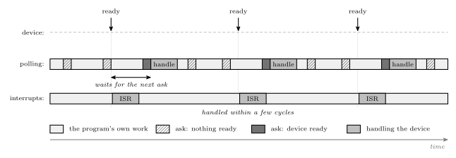
Figure 62: The same three device events handled both ways. Polling: the CPU breaks off its own work at fixed intervals to ask whether the device is ready. Most asks find nothing (hatched), and an event waits for the next ask before it is noticed, so how quickly it is handled depends on how often the program asks. Interrupts: the CPU does its work without asking, and each event diverts it into the handler within a few cycles. No time is spent asking, and the response does not depend on how long the main loop is. The work done is the same in both rows; what differs is the time wasted asking and the delay before each event is handled.
Interrupts are more efficient for the CPU, and they change the flow of control, which is where their cost lies.
A fourth way to leave the sequence
Normally the PC just increments. avr-branches-and-jumps and procedures-and-the-stack cover the instructions that change it. An interrupt changes it too, but without any instruction asking:
| Triggered by | Where the new PC comes from | Comes back? | |
|---|---|---|---|
| Branch | an instruction, if a flag says so | an offset in the instruction | no |
| Jump | an instruction | the instruction | no |
| Procedure call | an instruction (call) |
the instruction | yes: ret pops the return address call pushed |
| Interrupt | a device, between any two instructions | a table, indexed by which device | yes: the return-from-interrupt instruction pops the address the hardware pushed |
| Trap | an instruction that produces an exceptional result | a table, indexed by which error | not always |
The useful way to see an interrupt is as a procedure call that the hardware makes. The mechanism is the same: push the return address, load the PC, and pop it back at the end. The difference is that the program never asked for it, and that one difference produces all three of the issues below.
The three issues
Any interrupt mechanism has to answer three questions.
- How does the CPU know where the ISR is? A call names its target, but an interrupt does not, so the address must be found from the source. The CPU looks in an interrupt vector table, often at the beginning of memory. The table holds either the address of each handler, which the CPU loads into the PC, or a jump instruction to each handler, in which case the CPU loads the PC with the entry’s own address and executes the jump. The AVR does the second. Vector is used both for the interrupt’s number (its index in the table) and for the address of its handler, and it is worth checking which is meant.
- How are the registers preserved? All of them, including the status register. The handler must save copies of any register it uses before using it, and restore them before it returns. Many CPUs save the status register automatically; the AVR does not, so the handler must save it itself if it would change it. The result is transparency, below.
- What happens if another interrupt arrives while one is being serviced? Either it waits, or it interrupts the handler. See Nesting and priority, below.
The sequence of actions
From the device’s request to the resumed program there are fourteen steps, shared between the hardware and the ISR:
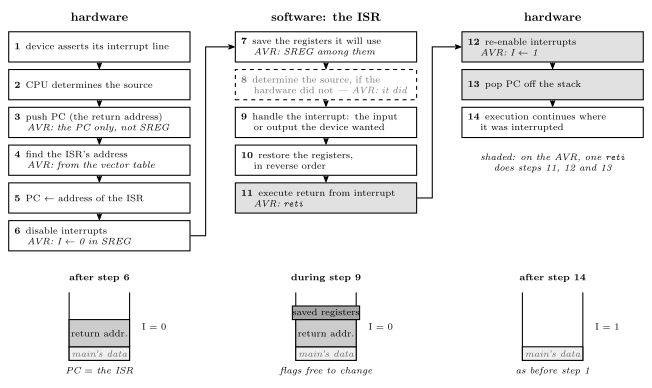
Figure 63: The fourteen steps of an interrupt, in the three phases the hardware and the ISR take turns at, with the state of the machine after each phase underneath. The hardware does the first six: it saves only the return address, finds and enters the handler, and turns interrupts off. The ISR saves what it will use, does the I/O and restores what it saved. The return-from-interrupt instruction then hands back to the hardware, which turns interrupts on and pops the return address. The notes in italics are the AVR’s version of each step. The shaded steps 11 to 13 are a single AVR instruction, reti, and step 8 rarely arises on the AVR (dashed), because every source has its own vector and so the ISR knows which one fired; only a pin-change handler, whose vector covers a whole port, still has to find which pin changed. The stack after step 14 is exactly as it was before step 1, and that is what transparency requires.
Three things in the sequence are worth holding on to:
- The hardware saves as little as it can. It pushes only the return address, and everything else is the ISR’s job. That keeps the entry fast, and it means an ISR that uses nothing need save nothing.
- Interrupts are off from step 6 to step 12. That is the default answer to issue 3: a second request simply waits until the handler has returned. On the AVR, off is the I bit of the status register being 0 (avr-architecture).
- Return from interrupt is not the same as return from procedure. It has to undo step 6 as well as step 3. A handler that ends with a plain
retgoes back to the right place but leaves interrupts disabled for good.
Transparency
When the ISR finishes, the computer is in the same state as it was before the interrupt. That is transparency, and it is the answer to issue 2. It matters more for an ISR than for a procedure because the interrupted code has no chance to prepare. A caller knows where its calls are and can agree with the procedure which registers it may use. An interrupt can land between any two instructions, including these two:
    cp   r16, r17        ; sets Z if r16 == r17
                         ; <- an interrupt here
    breq equal           ; reads Z
If the ISR does anything that sets flags — a dec, an andi, a cp of its own — and does not restore the status register, breq reads the ISR’s Z instead of the one cp produced. The program then takes the wrong branch, but only on the rare occasions the interrupt lands in that one gap. A bug like that can survive a great deal of testing. So the status register is the one register a handler must always consider, even if it touches nothing else. Whether an instruction changes it is listed per instruction in the instruction set reference (avr-instructions).
Nesting and priority
For an interrupt that arrives while an ISR is running, there are three policies:
- Disable interrupts during an ISR. The simplest: the second request waits (its flag stays set) and is serviced after the first handler returns. On CPUs that save the status register automatically, the global interrupt enable flag is among the bits the return-from-interrupt instruction restores, so it comes back on by itself. This is the AVR’s default.
- Prioritise. Higher-priority interrupts may interrupt lower-priority handlers, but not the other way round and not at the same level. Urgent devices are never kept waiting behind unimportant ones, and an unimportant device can never delay an urgent one. Many CPUs support this; the AVR does not.
- Re-enable interrupts inside the ISR. Any interrupt may then interrupt the handler, regardless of priority. The AVR allows this if the handler executes
sei.
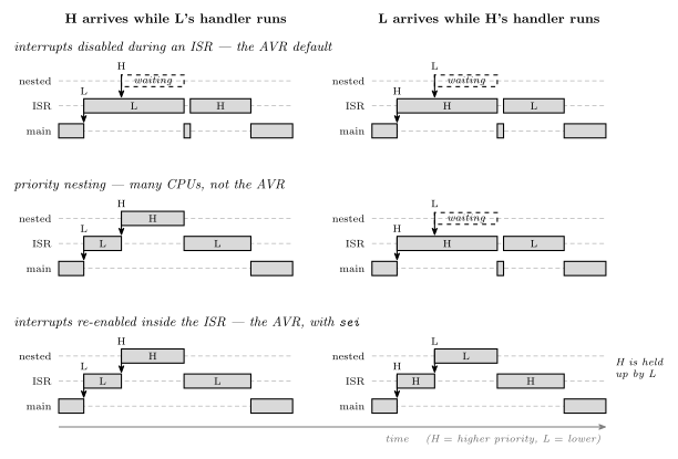
Figure 64: The three policies for an interrupt that arrives while another is being handled, in the two cases that tell them apart. In each panel, code on a higher lane has interrupted the code below it, and a dashed box is a request that is waiting. With interrupts disabled during an ISR, whichever handler started first finishes first, and the other waits for it in both cases. With priority nesting, the urgent request (H) cuts into the less urgent handler (L) but never the reverse, which is the behaviour one would want and the one the AVR does not provide. With interrupts re-enabled inside the handler, any request cuts in immediately, so in the right-hand case the urgent handler is itself held up by the less urgent one.
On the AVR, then, priority only decides the order in which waiting interrupts are serviced. It matters only when two or more are waiting at once, for instance because they arrived during another handler. The highest-priority one, the one with the lowest vector, goes first. It never lets an urgent interrupt cut into a running handler. The one way to get nesting is to re-enable interrupts inside the handler, and then priority plays no part at all. Both cases are traced, with the I bit, in 2026-09-21-interrupts.
The practical consequence is a rule: keep ISRs short. While any handler runs, every other interrupt waits. A handler that busy-waits for 10 ms delays every other device by 10 ms, and a timer tick that arrives twice during that time is serviced only once, because a flag can record that an event happened but not how many times.
Traps
Traps are software interrupts: interrupts caused by events in the software rather than in the hardware, and specifically by exceptional events, such as
- overflow,
- divide by zero, and
- an undefined opcode.
They relate to error checking the way interrupts relate to polling. Without traps, a program that must not overflow has to test after every arithmetic instruction, which is polling for errors. With them, the hardware watches, and the program is diverted only when the error actually happens. Traps save continually checking for errors.
Trap handlers don’t always return to the original program. After a division by zero or an undefined opcode, there is often no sensible instruction to continue with. Under an operating system the usual outcome is that the program is ended.
| Interrupt | Trap | |
|---|---|---|
| Caused by | a device, outside the program | the instruction being executed |
| When | at an unpredictable point in the program, asynchronously | at the same instruction every time, given the same data |
| Returns? | always, to the interrupted instruction’s successor | not always |
The AVR does not provide traps. Overflow sets V in the status register and it is up to the program to branch on it (avr-branches-and-jumps), and the AVR has no divide instruction to fail. But it is possible to generate hardware interrupts from software, by writing to an external interrupt pin configured as an output (avr-interrupts).
Pitfalls
- Assuming priority means pre-emption. On the AVR it does not: a higher-priority interrupt waits for a lower-priority handler to finish, like any other.
- Not saving the status register in a handler that changes flags. The symptom is an interrupted comparison going the wrong way, rarely and irreproducibly.
- Long handlers. Every other interrupt waits while one runs, and repeated events during the wait are merged into one.
- Variables shared between a handler and the main program that the compiler is allowed to cache. In C they must be
volatile(avr-interrupts). - Returning with
retinstead of the return-from-interrupt instruction: the program continues, and interrupts never come back on.
See also
- avr-interrupts — the ATmega324A’s vector table, ISRs in assembly and C, enabling an interrupt,
volatile, a complete timer-interrupt program - 2026-09-21-interrupts — Lecture 17, with the priority cases traced and worked questions
- procedures-and-the-stack —
call,retand the stack the return address goes on - avr-branches-and-jumps — the other ways the PC leaves its sequence
- avr-timers-and-counters — polling a timer flag, the thing interrupts replace
- software-timers — a tick interrupt as the program’s clock, and why busy waiting is the thing to avoid
- avr-usart · avr-spi · analog-to-digital-conversion — three devices that can be polled or left to interrupt
- fetch-decode-execute-cycle — the PC’s normal behaviour, increment and fetch
Procedures and the Stack
What a procedure is at the machine level, how call and ret get into it and back out, and the stack — the structure that makes returning possible from any depth of nesting, holds saved registers and arguments, and has to be set up before any of that works. First met in 2026-09-14-flow-of-control; branches and jumps are in avr-branches-and-jumps, and data memory, where the stack lives, is in memory-models and avr-architecture.
Procedures
A procedure is a group of instructions that performs some task, which
- may have operands — arguments or parameters,
- may produce result(s),
- can be invoked (called) from multiple places in a program — even from within itself, a recursive procedure — and
- after invocation, control returns to the statement after the call.
It is the same thing as a C function (c-language-basics), a Python function, a Java method, or a subroutine; the names differ by language, the mechanism does not. Good use of procedures is most of what makes a program of any size readable, and the AVR C compiler turns every function into exactly what follows.
The return is the part with machinery behind it. A jump goes somewhere; a call goes somewhere and remembers where it came from, so that a ret at the far end can come back — to a different place each time, depending on who called.
call and ret
| Instruction | Size | Cycles | |
|---|---|---|---|
call label |
direct call — target is an absolute address | 32-bit | 4 |
rcall label |
relative call — target is PC ± 2 K words | 16-bit | 3 |
icall |
indirect call — target is the address in Z | 16-bit | 3 |
ret |
return to the instruction after the most recent call | 16-bit | 4 |
The three calls mirror jmp, rjmp and ijmp exactly — same reach, same sizes — and each costs one cycle more than its jump. That cycle is the push. What a call does, in order:
- compute the return address — the address of the instruction after the call;
- push it onto the stack;
- load the PC with the target.
And ret undoes it: pop the top of the stack into the PC. Nothing in the procedure needs to know who called it, because the address to go back to was left on the stack by the caller.
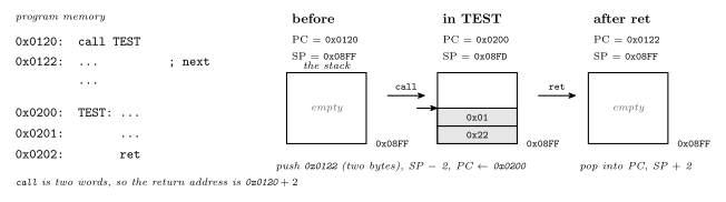
Figure 65: A call and its return, followed through the three registers involved. The PC, the stack pointer and the top of the stack are shown before the call, during the procedure and after the return, with example addresses. call records the address of its own successor on the stack and lowers the stack pointer by two, because a program-memory address needs two bytes; then it loads the PC with the procedure’s address. ret reverses both steps and execution resumes at the recorded address, which is the instruction after the call. The procedure body never touches the return address, so it does not matter what the procedure does in between, provided it leaves the stack as it found it.
Why a stack
The return address has to be stored somewhere. There are three candidates:
| Where | Fails when |
|---|---|
| A single fixed register or memory address for all calls | a procedure calls another procedure — the second call overwrites the first’s return address, and the outer procedure can never return |
| One memory location per procedure | a procedure calls itself — recursion needs two live return addresses for one procedure |
| A stack | never, until memory runs out |
A stack is a last-in, first-out store: push puts a value on top, pop takes the top value off. Calls and returns nest — the most recent call is always the first to return — so a stack of return addresses always has the right one on top. Nested calls are drawn step by step in 2026-09-14-flow-of-control.
The AVR stack
On the AVR the stack is simply a region of data memory (memory-models), and the stack pointer is a 16-bit address held in two I/O registers, SPH:SPL, that says where the top currently is. Two conventions fix how it works:
- The stack grows downward. A push stores at the address in
SPand then decrementsSP; a pop incrementsSPand then loads from it. SoSPalways points at the next free cell, just below the most recently pushed byte. - It starts at the top of SRAM. Program variables are allocated from the bottom of SRAM upward; the stack is started at the last address,
RAMEND(0x08FFon the ATmega324A), and grows down toward them. Neither has to know in advance how much room the other needs.
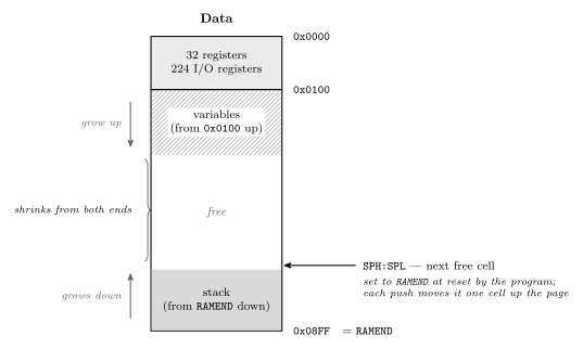
Figure 66: Where the stack lives in the ATmega324A’s data memory. The general-purpose registers and I/O registers occupy the first 256 addresses; SRAM begins at 0x0100. Global variables are laid out from the bottom of SRAM upward, and the stack starts at the top, RAMEND, and grows downward toward them, with SPH:SPL holding the address of the next free cell. The gap between them is the free memory, and it shrinks from both ends: every nested call, every push and every local variable of a running function takes cells off the top, and the stack overflows when it reaches the variables — silently, since nothing checks. That is why the stack pointer must be set to RAMEND before the first call: the reset value would put it somewhere else entirely.
Initialising the stack pointer
An assembly program must initialise the stack before using it. These four lines belong at the top of RESET: in any program that calls anything:
.def temp=r16
    ldi  temp, low(RAMEND)
    out  SPL, temp
    ldi  temp, high(RAMEND)
    out  SPH, temp
RAMEND is defined by the device include file (avr-io-ports), and low()/high() split the 16-bit value because SPL and SPH are two separate 8-bit I/O registers. In C the compiler emits this itself as part of the start-up code that runs before main; it is one of the things a C program on the AVR gets for free and an assembly program does not. The RESET template in avr-program-structure does not include it only because nothing in the Lab 10 programs made a call.
push and pop
The two stack instructions are also available directly:
| Cycles | ||
|---|---|---|
push rr |
store rr at SP, then SP ← SP − 1 |
2 |
pop rd |
SP ← SP + 1, then load rd from SP |
2 |
Their main use is saving registers a procedure is about to clobber, so that the caller gets them back unchanged:
TEST:
    push r16           ; save what the caller had in r16 and r17
    push r17
    ...                ; use r16, r17 freely
    pop  r17           ; restore — in REVERSE order
    pop  r16
    ret
The order matters because the stack is LIFO: the last register pushed is the first one back. And the count matters even more — every push must be matched by a pop before the ret, because ret pops whatever is on top and treats it as the return address. One push too many and the procedure returns to an address made of a register’s contents; one too few and it returns into the middle of the saved data.

Figure 67: Saving and restoring registers around a procedure body, with the stack drawn after each instruction. The return address is already on the stack when the procedure starts; the two pushes go on top of it, and the two pops must come off in the reverse order to land in the right registers. When ret runs the return address is back on top, exactly as call left it. If the pops were in the same order as the pushes, r16 and r17 would come back swapped; if one pop were missing, ret would pop the saved r16 and jump to whatever address that byte pair happened to spell.
Arguments and results
Arguments are passed and results returned in one of two ways: in registers, or on the stack.
- Registers are the fast way for a few small values: the caller puts the argument in an agreed register before the
call, the procedure reads it there and leaves its result in an agreed register for the caller to pick up. Agreement is the whole trick — both sides must use the same register, and a procedure that uses registers for arguments cannot also expect them preserved. - The stack is the general way: the caller pushes the arguments, then calls; the procedure finds them on the stack just above the return address, and results can be returned the same way or in registers. The return address, the arguments and any saved registers and locals together are the procedure’s stack frame. It costs pushes and pops, but it works for any number of arguments and for recursion, since every live call has its own frame.
The AVR C compiler uses both: the first few arguments of a function travel in registers, r24 down, and the rest on the stack, and a function’s local variables live in its stack frame. Those details are the compiler’s convention, and they are why a C function call is not free — see the main costs in c-language-basics.
A C function’s stack frame
A C compiler puts a function’s local variables in its stack frame, next to the return address and any arguments passed on the stack. The frame is pushed when the function is called and popped when it returns. A local therefore exists only while its call is running, and each call, including each level of a recursion, gets its own copy at its own address. An optimising compiler keeps a small local in a register when it can. The frame is where it goes when it needs memory, and the lifetime is the same either way.
In address order, from high to low, which is the order they are pushed:
- arguments, pushed by the caller before the call, if any are passed on the stack;
- the return address, pushed by
call; - locals, made by the function itself when it starts.
A static local is not in the frame. It is stored with the globals, at a fixed address, so it outlives the call and still holds its value the next time the function runs. Globals sit at the bottom of SRAM, the heap grows up above them, and the stack grows down from RAMEND. A stack that grows far enough to meet the heap has overflowed. How the compiler lays out the whole data memory is in compilation-and-linking.
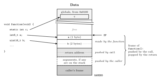
Figure 68: The stack frame of a C function while it runs, with the lowest address at the top as in the course’s memory maps. The caller pushed any stack arguments, call pushed the return address, and the function made room for its locals a and b above that. SP points at the next free cell, just above the frame. When the function returns, the whole frame is popped and SP goes back to where it was before the call, so a and b no longer exist. The static local c is not in the frame at all. It is stored among the globals at a fixed address, which is why it keeps its value from one call to the next.
The stack and interrupts
An interrupt uses the same stack in the same way. The hardware pushes the return address exactly as call would, and the handler’s reti pops it, like ret (avr-interrupts, 2026-09-21-interrupts). Three things follow:
- The stack pointer must be set before interrupts are enabled, not merely before the first
call. An assembly program with no procedures at all still needsSPinitialised once it uses an interrupt. - A handler’s pushes and pops must balance, and it must restore every register it uses. This is the same rule as for a procedure, but stricter: an interrupt can arrive between any two instructions, so there is no caller to agree anything with (polling-and-interrupts).
- Every interrupt that is being handled holds stack space: two bytes of return address plus whatever its handler pushes, and more again if handlers are allowed to nest.
Pitfalls
- Forgetting to initialise
SPin an assembly program. The firstcallpushes to wherever the reset value points; theretthen reads garbage. In C, not a concern. - Unbalanced push/pop inside a procedure — see Figure 67.
retdoes not check what it pops. - Stack overflow. Deep recursion, or big local arrays in C, walk the stack down into the heap and the variables. Nothing on the chip detects it; the symptom is variables changing value for no visible reason.
- Returning a pointer to a local. The local’s frame is popped by the return, so the pointer points at stack space that the next call will reuse.
- Clobbering the caller’s registers. A procedure that uses
r16without saving it changesr16for whoever called it. Either save and restore, or document which registers the procedure destroys — and be consistent.
See also
- avr-branches-and-jumps —
jmp,rjmp,ijmp, and the conditional branches - avr-program-structure — the
RESETtemplate the stack initialisation goes into - memory-models · avr-architecture — data memory,
RAMEND, and the I/O registersSPH/SPL - avr-instructions —
push,pop,call,retamong the rest - c-language-basics — functions in C, which compile to exactly this
- compilation-and-linking — where the compiler puts globals, locals, statics and the heap · 2026-10-15-compilation-and-linking — Lecture 22
- avr-interrupts · polling-and-interrupts — the same stack, used by the hardware
- 2026-09-14-flow-of-control — Lecture 15 · 2026-09-21-interrupts — Lecture 17, the stack under interrupts
Pulse Width Modulation
Pulse width modulation (PWM): making a digital output behave like an adjustable analog one by switching it on and off quickly and controlling what fraction of the time it is on. What the duty cycle is, why a fast pulse train has an average value, what that is good for, and how the AVR’s timer/counters generate it in hardware in their two fast PWM modes. From 2026-09-17-pulse-width-modulation; the timers themselves are in avr-timers-and-counters.
Duty cycle
A PWM signal is a periodic pulse — high for part of each period, low for the rest — and it is described by two numbers:
| Period \(T\) (s), or equivalently the frequency \(f = 1/T\) (Hz) | how often the pulse repeats |
| On-time \(T_{ON}\) (s) | how long the output is high in each period |
\[\text{duty cycle} = \frac{T_{ON}}{T} \times 100\%\]
The duty cycle is the percentage of the time the signal is on (high). 0 % is a constant low, 100 % a constant high, 50 % a square wave; modulating the pulse width means changing \(T_{ON}\) while \(T\) stays fixed. The five duty cycles are drawn in 2026-09-17-pulse-width-modulation.
Average value
If the pulses are fast enough, the signal looks like its average. The average of a periodic voltage is the area under one period divided by the period, and for a pulse between 0 and \(V\) the area is a rectangle:
\[V_{avg} = \frac{1}{T}\int_0^{T} v(t)\,dt = \frac{1}{T}\int_0^{T_{ON}} V\,dt = V \cdot \frac{T_{ON}}{T}\]
so the average voltage is the supply voltage times the duty cycle — 1.25 V at 25 % of 5 V, 2.5 V at 50 %. That is the whole point: a pin that can only ever be at 0 V or 5 V delivers, on average, any voltage between, set by a number in a register.
Fast enough means fast compared with the load. A motor’s inertia, a lamp’s thermal mass, the eye’s persistence or an explicit low-pass filter each smooth the pulses into their average; if the period is long enough for the load to follow the pulses, it sees pulses. So the frequency is chosen for the load once, and the duty cycle is the only thing varied afterwards.
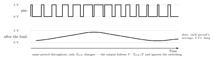
Figure 69: A PWM signal and what a slow load makes of it. Above, the pin’s actual voltage: pulses at a fixed period whose width steps up and then down. Below, the same signal after a low-pass filter — a motor’s inertia, an LED as the eye sees it, or a real RC network before a speaker — which cannot follow individual pulses and settles at their running average. The filtered output tracks the duty cycle and not the pulses, with a small ripple left over from the switching, and moving the duty cycle from period to period moves the output smoothly: an analog waveform out of a digital pin. The higher the PWM frequency relative to the load’s response, the smaller the ripple.
What it is for
Generating signals that look analog from a purely digital source. The AVR has no digital-to-analog converter, and PWM plus the load’s own smoothing is how it gets an analog-looking output:
- Varying the brightness of lights and LEDs — fading is ramping the duty cycle; the eye averages
- Motor control — the average voltage sets the speed of a DC motor; the inertia averages
- Generating audio, with appropriate filtering — vary the width from period to period so the average traces a waveform, filter off the pulses, and what is left is the tone
PWM on the AVR: fast PWM
A timer/counter (avr-timers-and-counters) generates PWM with no software involvement at all. The mechanism is the same in every mode: the count is a sawtooth, a compare register draws a horizontal line across it, and the pin changes state where they cross — once at the match and once more when the count wraps. Moving the compare value moves the crossing along the ramp, which moves one edge of the pulse. That is the modulation.
The waveform generation mode bits pick what the top of the sawtooth is, and the compare output mode bits pick which way the pin switches at the crossing.
Mode 3 — top fixed at 255 (WGM[2:0] = 011)
The count runs 0 to 255 and wraps: every period is exactly 256 ticks, so
\[T_{tick} = \frac{1}{CLK/PRE} \qquad T = \frac{256}{CLK/PRE} \qquad f = \frac{CLK}{256 \cdot PRE}\]
and the frequency is set entirely by the prescaler. Both compare registers are free to make pulses, so one timer gives two independent PWM outputs at the same frequency, OCnA and OCnB. With the compare value at 191 the pin is high for 64 of the 256 ticks in inverting mode, a 25 % duty cycle — the worked example in 2026-09-17-pulse-width-modulation.
Mode 7 — top in OCRnA (WGM[2:0] = 111)
The count wraps when it reaches OCRnA instead of 255: the period is OCRnA + 1 ticks and can be chosen,
\[T = \frac{1 + OCRnA}{CLK/PRE} \qquad f = \frac{CLK}{(1 + OCRnA) \cdot PRE}\]
The pulse is then made on the other compare unit, OCRnB against the shorter ramp. The price of choosing the frequency is that compare unit A is spent on it: one PWM output per timer, and OCnA can at most toggle on each wrap. With OCRnA = 127 and OCRnB = 95 the period is 128 ticks and the inverting output is high for 32 of them — again 25 %.
Both are cases of the master formula \(f = CLK / (PRE \cdot (TOP + 1))\) with \(TOP = 255\) or \(TOP = OCRnA\).
Inverting and non-inverting
The compare output mode bits COMnx1:0 decide what the crossing does to the pin in fast PWM:
COMnx1:0 |
On compare match | At the wrap (BOTTOM) | Pulse is high for | Duty cycle |
|---|---|---|---|---|
10 — non-inverting |
clear OCnx |
set OCnx |
OCRnx + 1 ticks, from the wrap to the match |
\(\dfrac{OCRnx + 1}{TOP + 1}\) |
11 — inverting |
set OCnx |
clear OCnx |
\(TOP - OCRnx\) ticks, from the match to the wrap | \(\dfrac{TOP - OCRnx}{TOP + 1}\) |
01 |
toggle OCnA — mode 7 only, and only unit A |
a square wave at half the wrap rate | 50 % | |
00 |
pin disconnected — ordinary port pin |
The two outputs are complements: the same crossing, opposite polarity, and their on-times add to a full period. Non-inverting is the natural choice — a bigger number means a wider pulse — and is what duty cycle = (OCR + 1) / 256 refers to.
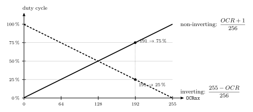
Figure 70: How the compare value maps to duty cycle in mode 3, for the two polarities. In non-inverting mode the pulse runs from the wrap to the match, so it is \(OCR + 1\) ticks of 256 and the duty rises linearly with the register from just under 0.4,% at 0 to 100,% at 255. In inverting mode the pulse runs from the match to the wrap, so it is \(255 - OCR\) ticks: the same line reflected, 100,% at 0 down to 0,% at 255. The two always sum to 100,%. Neither polarity reaches both ends: non-inverting cannot give a true 0,% (a compare value of 0 still gives one tick high) and inverting cannot give 100,%; a program that needs the output fully off disconnects the pin instead.
Setting it up
Four registers, all from the header names (c-preprocessor-and-avr-headers, bit-masking) — timer 0, mode 3, non-inverting on OC0B (PB4), clock ÷ 64, 25 % duty:
DDRB   |= (1<<4);                              /* OC0B is PB4: the timer decides what, DDR decides whether */
TCCR0A  = (1<<COM0B1) | (1<<WGM01) | (1<<WGM00); /* non-inverting on B; fast PWM, TOP = 255 */
TCCR0B  = (1<<CS01) | (1<<CS00);               /* clock / 64: 8 MHz / (256 * 64) = 488 Hz */
OCR0B   = 63;                                  /* (63 + 1) / 256 = 25 % */
After this the CPU never touches the pin; changing the duty cycle is one assignment to OCR0B, and it takes effect at the next wrap. The compare registers are double buffered in the PWM modes: a value written is held back and loaded when the count wraps, so a pulse already under way is never cut short. The frequencies mode 3 can produce at 8 MHz are one per prescaler tap:
| Prescaler | \(f = 8\,\text{MHz} / (256 \cdot N)\) |
|---|---|
| 1 | 31.25 kHz |
| 8 | 3.91 kHz |
| 64 | 488 Hz |
| 256 | 122 Hz |
| 1024 | 30.5 Hz |
For an LED anything from 122 Hz up is flicker-free; for audio the 31.25 kHz setting is the one above hearing. If a frequency between the taps is needed, mode 7 with an OCR0A chosen from the master formula.
Phase correct PWM
The other family of PWM modes has the counter count up and then down — a triangle rather than a sawtooth — and switch the pin at the compare value on both slopes. The pulse is then symmetric about the peak of the triangle, so the centre of every pulse stays at the same point in the period as the width changes, instead of the leading edge staying fixed and only the trailing edge moving. That is smoother for motor control, where the timing of the current pulse relative to the period matters; the cost is a period twice as long for the same top, so half the frequency. Timer 1 adds a phase and frequency correct variant on top. The two families are drawn side by side in 2026-09-17-pulse-width-modulation. This course uses fast PWM only.
See also
- avr-timers-and-counters — the timers: registers, clock select, prescaler, modes, the master formula
- week8-lab-avr-timers — Lab 12:
WGM,CSandCOMbit by bit; the formula worked for a toggling pin - week9-lab-avr-pwm — Lab 13: two LEDs faded on timer 0, and a tone of adjustable pitch and duty cycle on timer 1
- 2026-09-17-pulse-width-modulation — Lecture 16 · 2026-09-14-flow-of-control — Lecture 15
- avr-io-ports — the
DDRbit the timer still needs · timing-diagrams — how the waveforms are drawn
Serial Communication
Sending data between devices one bit at a time, and how the receiving end makes sense of what arrives: serial against parallel, synchronous against asynchronous, the UART frame, parity, how a receiver samples the line, and baud rate. Then the synchronous serial buses, where one master clocks data to and from several slaves: SPI and I²C, compared with the UART, and bit bashing for when there is no hardware for a standard. The AVR’s hardware is in avr-usart and avr-spi. First met in 2026-09-24-serial-io and 2026-10-05-more-io.
Serial and parallel
| Parallel | Serial | |
|---|---|---|
| Wires carrying data | one per bit | one |
| How a byte travels | all 8 bits at once | 8 bits one after another |
| Cost | many pins and wires | time: a byte takes 8 bit times |
Inside a chip, data moves in parallel: a port is eight pins, a register is eight flip-flops. Between devices, pins and wires are what is scarce, so nearly every link is serial. The conversion at each end is the job of a shift register (shift-registers): load a byte in parallel and shift it out one bit at a time to send, shift bits in and read the byte out in parallel to receive.
By convention the sending end of a link is Tx and the receiving end is Rx. A device that does both has one of each, and two such devices are joined crossed over: each one’s Tx goes to the other’s Rx.
Synchronous and asynchronous
A receiver has to know when to look at the data wire, as well as what is on it. There are two ways to tell it.
Synchronous: one end sends a clock on a second wire. The receiver reads the data wire on each clock edge. Nothing has to be agreed in advance about speed, beyond the fastest the receiver can follow. SPI, the Serial Peripheral Interface, and I²C both work this way (below).
Asynchronous: there is no clock wire. Each end has its own clock, the two agree on the speed beforehand, and the receiver recovers the exact timing from the data stream itself. That only works if the stream is guaranteed to contain edges to time against, so the data is encoded:
| Encoding | How it guarantees edges | Used by |
|---|---|---|
| start and stop bits | every character begins with a fall from 1 to 0 | UART |
| 4B/5B, 8B/10B | every 4 or 8 bits are replaced by a 5- or 10-bit code that never has a long run | fast network links |
| bit stuffing | an opposite bit is inserted after a run of identical bits | USB at low and full speed |
A UART is a Universal Asynchronous Receiver and Transmitter. A USART can also work synchronously. The pictures of all four cases are in 2026-09-24-serial-io.
The UART frame
A UART sends data in frames. Between frames the line rests at 1, the idle level. A frame is:
| Order | Field | How many | Value |
|---|---|---|---|
| 1 | start bit | 1 | always 0 |
| 2 | data bits | 5 to 9 | the data, least significant bit first |
| 3 | parity bit | 0 or 1 | chosen to make the count of 1s even or odd |
| 4 | stop bits | 1 or 2 | always 1 |
Why each part is there:
- The start bit is 0 because the idle line is 1. The fall from 1 to 0 is the one event the receiver can be sure of, and everything else is timed from it.
- The stop bit is 1 so that the line is back at the idle level when the frame ends. Whatever the last data bit was, the next start bit is then a fall again.
- The data bits go least significant first. A receiver that assumes the opposite reads every byte bit-reversed.
The format is usually written as three items: data bits, parity (N for none, E for even, O for odd), stop bits. 8N1 is 8 data bits, no parity, 1 stop bit, and is by far the commonest.
Worked: the letter s
A character is sent as its ASCII code (c-language-basics). The letter s is 115, 0x73, 0111 0011. In 8N1 the line carries, in time order:
| start | b0 | b1 | b2 | b3 | b4 | b5 | b6 | b7 | stop |
|---|---|---|---|---|---|---|---|---|---|
| 0 | 1 | 1 | 0 | 0 | 1 | 1 | 1 | 0 | 1 |
Read left to right, the data bits are 1100 1110, the byte written backwards.
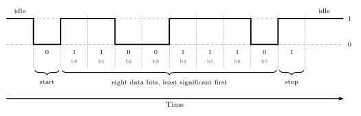
Figure 71: The letter s, 0x73, on the wire as an 8N1 frame. Time runs left to right and each cell is one bit time. The line idles at 1, falls for the start bit, carries the eight data bits least significant first, and returns to 1 for the stop bit. Written most significant bit first the byte is 0111 0011; the wire carries it in the opposite order.
Parity
The parity bit lets the receiver detect that a frame was damaged. The two ends agree on the kind:
- Even parity: the number of 1s in the data bits and the parity bit together is even.
- Odd parity: that number is odd.
To send: count the 1s in the data. Choose the parity bit that makes the total the agreed kind.
To check: count the 1s in the data and the parity bit as received. If the total is the wrong kind, there was an error.
| Data | 1s in the data | Even parity bit | Odd parity bit |
|---|---|---|---|
0xA7 = 1010 0111 |
5 | 1 | 0 |
0xA9 = 1010 1001 |
4 | 0 | 1 |
0x73 = 0111 0011 |
5 | 1 | 0 |
0x00 = 0000 0000 |
0 | 0 | 1 |
The even parity bit is the XOR of the data bits (logic-gates): XOR is 1 exactly when an odd number of its inputs are 1, which is exactly when a 1 is needed to make the total even. The odd parity bit is its complement.
Worked check. 0xA9 arrives with parity bit 1 on an even-parity link. The data has four 1s, and the parity bit makes five. Five is odd, so the frame is in error.
What parity cannot do:
- It cannot say which bit is wrong, so it cannot correct anything. The frame has to be discarded or sent again.
- It misses any even number of flipped bits. Two flips cancel and the count comes out right.
Detecting and correcting needs several check bits arranged so that the pattern of failed checks points at the wrong bit. That is a Hamming code, and it is not part of a UART frame.
Sampling: finding the bits without a clock
The receiver knows the bit time from the agreed baud rate. What it does not know is when a frame will start. It finds out by watching:
- It samples the line many times per bit: 16 on the AVR.
- While the line is idle, every sample is 1. A sample of 0 means a start bit may have begun, and the receiver starts counting samples from there.
- It reads the three samples at the centre of each bit time and takes the majority. For the first bit time the answer must be 0, or the fall was only noise and the receiver goes back to waiting.
- It carries on, one bit time after another, for the data bits, the parity bit if there is one, and the stop bit.
- The stop bit must read 1. If it reads 0 the frame is wrong: a framing error, usually a sign that the two ends disagree about the baud rate or the format.
The picture is in 2026-09-24-serial-io.
Why the clocks need not match exactly. Suppose the receiver’s clock is slightly slow. Each sampling point is then a little later within its bit than the one before, and by the last bit of the frame the lateness has added up. As long as the total stays under half a bit time, every sample still lands inside the right bit. A 10-symbol frame gives the error about ten bit times to build up, so the two clocks have to agree to within a few percent. At the next start bit the count starts again from the new falling edge and the accumulated error is gone. That re-timing on every frame is what the start bit is for.
Baud rate and bit rate
Baud rate = symbols per second. Bit rate = useful data bits per second.
On a UART line a symbol is one bit time, and start, parity and stop bits are symbols that carry no data. So the bit rate is always lower than the baud rate, by the fraction of the frame that is data.
| Format | Symbols per frame | Data bits | Data fraction | At 9600 baud |
|---|---|---|---|---|
| 8N1 | 10 | 8 | 80 % | 7680 bit/s, 960 bytes/s |
| 8E1 or 8O1 | 11 | 8 | 73 % | 6982 bit/s, 873 bytes/s |
| 8N2 | 11 | 8 | 73 % | 6982 bit/s, 873 bytes/s |
| 7E1 | 10 | 7 | 70 % | 6720 bit/s, 960 characters/s |
The method: frames per second is the baud rate divided by the symbols per frame, and bits per second is that times the data bits per frame. For 8N1 at 9600 baud, \(9600 / 10 = 960\) frames per second and \(960 \times 8 = 7680\) bits per second.
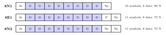
Figure 72: Three frame formats, one cell per symbol. Shaded cells carry data and white cells are framing. Every format here carries eight data bits, so adding a parity bit or a second stop bit makes the frame eleven symbols long instead of ten, and at the same baud rate fewer frames fit into a second.
The standard baud rates are 2400, 4800, 9600, 14400, 19200, 28800, 38400, 57600 and 115200.
Both ends must agree
Four settings define a UART link, and none of them is sent over it:
- the baud rate;
- the number of data bits;
- the parity: none, even or odd;
- the number of stop bits.
A terminal program on a PC asks for all four, plus which serial port to use. If the two ends differ, the receiver still samples the line and still produces bytes. They are just the wrong bytes, sometimes with framing or parity errors flagged and sometimes not. Garbled characters on a terminal almost always mean a mismatch here, most often the baud rate.
RS232
A serial standard more than 40 years old and still in use, typically on a 9-pin D-sub connector. Its frames are UART frames. Its voltages are not the microcontroller’s:
| Microcontroller pin | RS232 line | |
|---|---|---|
| logical 1 | 5 V | negative, −3 V to −15 V |
| logical 0 | 0 V | positive, +3 V to +15 V |
So RS232 is inverted and uses larger voltages of both signs. A level-converter chip such as the MAX-232 goes between an AVR pin and an RS232 line. Connecting the two directly does not work and can damage the pin.
RS232 is full duplex: there is a separate wire for each direction, so both ends can transmit at once. The standard defines many signals, and the smallest useful set is three: TxD, RxD and ground. Ground is needed because a voltage only has meaning against a reference both ends share.
Buses: masters and slaves
A UART joins exactly two devices. A bus is a set of wires shared by several, and that raises the question of who decides when a transfer happens.
- The master initiates and controls the transfer of data: it decides when a transfer starts, which device it is with and which way the data goes, and on a synchronous bus it drives the clock.
- A slave waits for requests and responds to the master. It never starts a transfer.
Some devices can be both, at different times. The AVR’s SPI and TWI ports can each be set up as a master or as a slave, and on an I²C bus more than one device may take a turn at being master. Memory can never be a bus master: all a memory can do is answer a read or a write of an address that something else has chosen. On a processor’s memory bus the CPU is the master.
Synchronous serial buses
Both buses here send a clock from the master alongside the data, so neither needs start and stop bits or an agreed baud rate. They differ in how the master picks which slave it is talking to.
SPI
The Serial Peripheral Interface has four signals: the clock SCK, a data wire each way, MOSI (master out, slave in) and MISO (master in, slave out), and an active-low select \(\overline{\text{SS}}\) for each slave. The master and the slave each hold an 8-bit shift register, and MOSI and MISO join them into a ring, so on every clock pulse one bit goes each way. Eight pulses swap the two bytes: every transfer is an exchange. Several slaves either get a select line each, or are daisy-chained on one select with the data passing through each in turn. All of this, with the AVR’s SPI port, is in avr-spi.
I²C and TWI
I²C, the Inter-Integrated Circuit bus, was created by Philips Semiconductor, now NXP. TWI, the Two-wire Interface, is Atmel’s name for it. There are two wires, and every device connects to both:
- SDA, serial data, which carries data in either direction, one way at a time;
- SCL, serial clock, driven by the master.
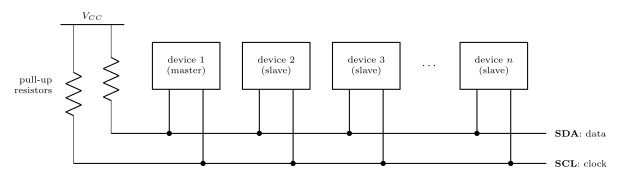
Figure 73: An I²C bus. Every device connects to the same two wires: SDA carries the data, in either direction, and SCL carries the clock from the master. No device ever drives a line high. Each can only pull a line low or let go of it, and the two pull-up resistors hold a line at 1 while nobody is pulling, so two devices can never fight over a line. Because every device hears every transfer, the master begins each one with the address of the slave it is for. A dot is a connection; where a lead crosses SDA without a dot there is no connection.
Why the pull-ups. Every output on the bus is open drain: it can connect its line to ground or leave it alone, and never connects it to \(V_{CC}\). A line is 1 when nobody is pulling it down and 0 when anybody is. Any number of devices can share a wire that way without two outputs ever fighting.
Addresses instead of select lines. Every device sees every transfer, so the master starts each one by sending the address of the slave it wants, and only that slave answers. Adding a device adds no wires.
On the ATmega324A the TWI uses PC0 as SCL and PC1 as SDA, and the datasheet describes it on pages 211 to 239 (2026-10-05-more-io).
UART, SPI and I²C compared
| UART | SPI | I²C / TWI | |
|---|---|---|---|
| Clock | none: both ends agree a baud rate | SCK, from the master | SCL, from the master |
| Data wires | TxD and RxD, one each way | MOSI and MISO, one each way | SDA, shared by both directions |
| Both directions at once? | yes | yes: every transfer is an exchange | no |
| Devices | two | one master, many slaves | many, some able to be master |
| Choosing a slave | no need: only two ends | a select line per slave, or a daisy chain | an address sent on the bus |
| Wires, besides ground | 2 | 3, plus a select per slave | 2 |
| On the ATmega324A | USART0 (PD0, PD1), USART1 (PD2, PD3) | one SPI port, PB4 to PB7 | one TWI port, PC0 and PC1 |
Bit bashing
Sometimes a microcontroller has no hardware support for a bus standard, or not enough interfaces of it. The standard can still be used by simulating it on general purpose port pins: the program sets and clears the output pins and reads the input pins itself, in exactly the order the standard lays down. That is bit bashing, also called bit banging.
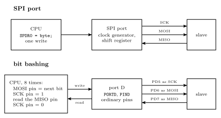
Figure 74: Who does the work. Above, with an SPI port: the program writes one byte to the data register and the port’s own clock generator and shift register produce all eight clock pulses and move all sixteen bits, while the CPU is free. Below, bit bashing the same transfer on three ordinary pins of port D: the CPU runs a loop that puts each bit on the MOSI pin, raises and lowers the SCK pin and reads the MISO pin, eight times over, through the port’s PORTD and PIND registers. The slave cannot tell the difference. The CPU is busy for the whole transfer, and the clock can go no faster than the loop.
Worked: an SPI master in software
Three spare pins of port D, plus one for the select, can be an SPI master in mode 0, most significant bit first, with nothing but the set, clear and test idioms of bit-masking:
#define BB_SS    4                 /* port D pins used for the software SPI */
#define BB_SCK   5
#define BB_MOSI  6
#define BB_MISO  7

void bb_init(void) {
    DDRD  |= (1<<BB_SS) | (1<<BB_SCK) | (1<<BB_MOSI);   /* outputs; MISO stays an input */
    PORTD |= (1<<BB_SS);                                /* nothing selected             */
    PORTD &= ~(1<<BB_SCK);                              /* the clock rests low          */
}

uint8_t bb_exchange(uint8_t out) {
    uint8_t in = 0;
    uint8_t i;

    for (i = 0; i < 8; i++) {
        if (out & 0x80) {                    /* put the top bit on MOSI           */
            PORTD |= (1<<BB_MOSI);
        } else {
            PORTD &= ~(1<<BB_MOSI);
        }
        out <<= 1;
        PORTD |= (1<<BB_SCK);                /* rising edge: both ends read       */
        in = (in << 1) | ((PIND >> BB_MISO) & 1);
        PORTD &= ~(1<<BB_SCK);               /* falling edge: the slave moves on  */
    }
    return in;
}
Used like the hardware version: pull BB_SS low, call bb_exchange once per byte, raise BB_SS. Reading MISO straight after raising SCK is safe, because the slave put that bit out on the previous falling edge, or when it was selected, and it stays put until the next falling edge.
What it costs.
- The CPU does everything. Each bit is several instructions, so the clock runs far slower than the 4 MHz the SPI port can make, and the program does nothing else meanwhile.
- Synchronous standards bash easily. The master makes the clock, so if the loop is held up between two edges, by an interrupt for instance, the transfer simply pauses. The slave waits for the next edge however long it takes.
- Asynchronous standards are harder. A bit-bashed UART has no clock to wait for, so every bit time has to be produced exactly, and an interrupt landing in the middle of a frame can wreck it.
Common mistakes
- Tx to Tx. The link is crossed: one end’s transmit pin goes to the other’s receive pin.
- Treating baud rate as bit rate. 9600 baud in 8N1 moves 7680 data bits a second, not 9600.
- Reading the bits most significant first. A UART sends bit 0 first.
- Leaving the parity bit out of the count. The rule is about the data bits and the parity bit together.
- Expecting parity to fix or locate an error, or to catch every error.
- Drawing the idle line at 0. Idle is 1, the start bit is 0, the stop bit is 1.
- Forgetting ground between two boards.
- Crossing SPI’s data wires. MOSI goes to MOSI and MISO to MISO: the names already say which end drives.
- Leaving out the pull-ups on an I²C bus. Nothing ever drives the lines high, so without them they never return to 1.
- Thinking memory could start a transfer. Memory is always a slave.
See also
- avr-usart — the ATmega324A’s USART: registers, baud-rate values, code and interrupts
- avr-spi — the ATmega324A’s SPI port: the exchange, timing, several slaves, registers, clock rate, code
- bit-masking — the set, clear and test idioms the bit-bashing code is made of
- shift-registers — parallel in, serial out, and the reverse
- logic-gates — XOR, which computes a parity bit
- timing-diagrams — how the waveforms here are drawn and read
- magnetic-disks — a disk sector, framed like a UART frame: preamble, data, ECC, gap
- io-board — the USB-serial device that joins the breadboard to a PC
- 2026-09-24-serial-io — Lecture 18 · 2026-10-05-more-io — Lecture 19
Seven-Segment Display
How a digit is shown on the IO board’s seven-segment display: the segment lettering, the byte that lights a pattern, the lookup table for all ten digits, and the common-cathode line that selects which of the two digits is lit. First met in 2026-09-10-more-c-programming-on-the-avr; the board’s header is in io-board and the port registers in avr-io-ports.
Segments
Seven bars lettered a to g, plus a decimal point dp:
| Segment | Position |
|---|---|
| a | top |
| b | upper right |
| c | lower right |
| d | bottom |
| e | lower left |
| f | upper left |
| g | middle |
| dp | the dot, lower right |
— clockwise from the top for a to f, then g across the middle. Each segment is an LED; a 1 on its line lights it.
The byte
The display is driven from one 8-bit port, one bit per segment, in this order:
| bit 7 | bit 6 | bit 5 | bit 4 | bit 3 | bit 2 | bit 1 | bit 0 |
|---|---|---|---|---|---|---|---|
| dp | g | f | e | d | c | b | a |
So the byte for a digit is read off by asking, segment by segment, whether it is lit. Two worked examples:
| Digit | Lit | dp g f e d c b a | Sum | Decimal |
|---|---|---|---|---|
| 0 | a b c d e f | 0 0 1 1 1 1 1 1 |
\(32 + 16 + 15\) | 63 |
| 2 | a b g e d | 0 1 0 1 1 0 1 1 |
\(64 + 16 + 8 + 3\) | 91 |
PORTA = 63; shows a 0; PORTA = 91; shows a 2. The 2 and both bytes are drawn in 2026-09-10-more-c-programming-on-the-avr.
All ten digits
The lookup table from the program below, decoded:
| Digit | Decimal | Binary (dp g f e d c b a) | Segments lit |
|---|---|---|---|
| 0 | 63 | 0011 1111 |
a b c d e f |
| 1 | 6 | 0000 0110 |
b c |
| 2 | 91 | 0101 1011 |
a b d e g |
| 3 | 79 | 0100 1111 |
a b c d g |
| 4 | 102 | 0110 0110 |
b c f g |
| 5 | 109 | 0110 1101 |
a c d f g |
| 6 | 125 | 0111 1101 |
a c d e f g |
| 7 | 7 | 0000 0111 |
a b c |
| 8 | 127 | 0111 1111 |
a b c d e f g |
| 9 | 111 | 0110 1111 |
a b c d f g |
Displays differ on whether 6 lights segment a, the top bar, and whether 9 lights segment d, the bottom bar. This table lights both, giving a hooked 6 and an underlined 9.
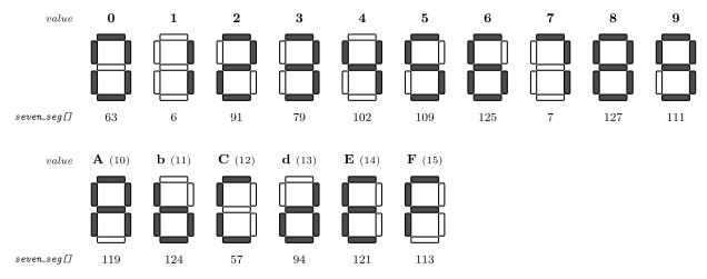
Figure 75: All sixteen values a nibble can hold, as seven-segment patterns, with the byte that produces each one in decimal underneath — the sixteen entries of the lookup table in order. Heavy segments are lit; the bit order is dp g f e d c b a with a at bit 0, so each number is read straight off the lit segments: 63 is every segment but g, 6 is b and c alone. The hex letters b and d are lowercase because their capitals would be indistinguishable from 8 and 0 on seven segments; A, C, E and F have no such clash.
Hex digits A–F
Four input bits hold 0–15, and the six values past 9 can be shown too, as hex letters. Two of them have to be lowercase: an uppercase B on seven segments is an 8, and an uppercase D is a 0.
| Value | Shows | Segments lit | dp g f e d c b a |
Decimal |
|---|---|---|---|---|
| 10 | A | a b c e f g | 0111 0111 |
119 |
| 11 | b | c d e f g | 0111 1100 |
124 |
| 12 | C | a d e f | 0011 1001 |
57 |
| 13 | d | b c d e g | 0101 1110 |
94 |
| 14 | E | a d e f g | 0111 1001 |
121 |
| 15 | F | a e f g | 0111 0001 |
113 |
With these appended the table has sixteen entries and every value a masked nibble can produce is a valid index, so the guard in the program below can go:
uint8_t seven_seg[16] = { 63,6,91,79,102,109,125,7,127,111,
                          119,124,57,94,121,113 };
This is Lab 11’s Task 2 (week8-lab-avr-c-programming), and the same table drives the hex adder of its Task 3.
The program
#include <avr/io.h>

/* Seven segment display values */
uint8_t seven_seg[10] = { 63,6,91,79,102,109,125,7,127,111};

int main(void) {
  uint8_t digit;

  /* Set port A pins to be outputs, port C pins to be inputs */
  DDRA = 0xFF;
  DDRC = 0;    /* This is the default, could omit. */
  while(1) {
    /* Read in a digit from lower half of port C pins */
    /* We read the whole byte and mask out upper bits */
    digit = PINC & 0x0F;
    /* Write out seven segment display value to port A */
    if(digit < 10) {
      PORTA = seven_seg[digit];
    } else {
      PORTA = 0;
    }
  }
}
Port A drives the eight segment lines; the low four bits of port C are the input digit. The loop reads the digit, masks off the upper nibble (bit-masking), looks the pattern up and writes it. The if guards the table — four bits can be 10–15, and seven_seg[10] is past the end of the array (c-pointers-and-arrays); those inputs blank the display instead.
Lookup table, not arithmetic. There is no formula that turns a digit into its segment pattern, so the program does not try: the ten answers are precomputed and indexed. It is the general pattern for any input-to-output mapping that is small and irregular, and it is what the array is for.
Two digits, one set of lines: CC
On the IO board the display has two digits but the header carries one set of segment pins — DP, G … A — plus one more, CC, the common cathode (io-board). The segment lines go to both digits; CC decides which one is actually lit:
CC |
Lit |
|---|---|
| 1 | left digit |
| 0 | right digit |
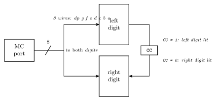
Figure 76: Why one port can drive two digits. The eight segment lines are wired to both digits in parallel, so both always receive the same pattern; the CC line selects which digit’s common cathode is connected to ground, and only that digit lights. One byte and one select bit therefore describe the whole display at any instant. To show two different digits the program alternates — left pattern with CC = 1, then right pattern with CC = 0 — fast enough that the eye sees both at once.
Writing a digit therefore takes two outputs: the segment byte on port A, and CC on whichever pin it is wired to. The program above drives a single digit and never touches CC; in Lab 11 CC is simply jumpered to a button, so pressing it moves the same digit across.
Display multiplexing
Showing a two-digit number means time-sharing the segment lines: write the tens pattern with CC = 1, wait, write the ones pattern with CC = 0, wait, repeat. Alternate fast enough — every millisecond, say — and persistence of vision merges the two into a steady two-digit display, each digit at half brightness because it is lit half the time. Slow the alternation to a few times a second and the trick becomes visible, with the digits taking turns. The waiting is a timer’s job (avr-timers-and-counters); the whole program, and a timing diagram of the two digits taking turns, is Lab 12’s Task 2 (week8-lab-avr-timers). Two things the ordering has to get right: write the segments before switching CC, so the newly selected digit never flashes the other digit’s pattern, and keep the tick regular, or one digit will look brighter than the other.
See also
- io-board — the header pins
CC DP G F E D C B A, and where the display sits on the board - avr-io-ports —
DDRA,PORTA,PINC - bit-masking —
PINC & 0x0F - c-pointers-and-arrays — the lookup table
- c-preprocessor-and-avr-headers — why
PORTAcan be assigned to - 2026-09-10-more-c-programming-on-the-avr — Lecture 14
- week8-lab-avr-c-programming — Lab 11: the display wired up, hex digits, the adder · week8-lab-avr-timers — Lab 12: display multiplexing on a timer tick · week9-lab-avr-interrupts — Lab 14: the display as a stopwatch
Shift Registers
Registers and shift registers are the simplest useful sequential circuits — groups of D flip-flops sharing a common clock.
Registers
- A register is a group of flip-flops. An \(n\)-bit register consists of \(n\) flip-flops and is capable of storing \(n\) bits.
- A register is a sequential circuit without any combinational logic — it is just the storage elements and their shared control lines.
- Registers are used to store binary information (data/instructions) inside a processor.
A 4-bit register:
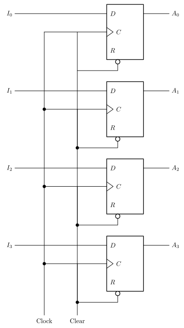
Figure 77: A 4-bit register (Mano, Digital Design, 3rd ed.). Four flip-flops, four parallel inputs, four parallel outputs, and exactly two shared control lines — no gate anywhere, which is what makes a register a sequential circuit without combinational logic. The pin labelling is Mano’s, which differs from the rest of the course: the clock input is lettered C rather than CLK and the asynchronous clear is lettered R, marked active-low by the bubble on the pin. The course uses several labellings for both (see the diagram-notation note).
| Signal | Connection |
|---|---|
| \(I_0 \ldots I_3\) | the four parallel data inputs, one to each flip-flop’s \(D\) input |
| \(A_0 \ldots A_3\) | the four parallel outputs, taken from each flip-flop’s \(Q\) |
Clock |
a single common line driven to the \(C\) (clock) input of all four flip-flops |
Clear |
a single common line driven to the \(R\) (reset) input of all four flip-flops, drawn active-low (bubble on the input) |
So on each rising clock edge all four flip-flops simultaneously capture their \(I\) inputs; asserting Clear forces all four outputs to 0 asynchronously (see flip-flops-and-latches for asynchronous SET/CLR).
Shift registers
A shift register is a register which is capable of shifting its binary information in one or both directions.
The 4-bit shift register example is built as a chain: the serial input \(SI\) feeds the \(D\) input of the first flip-flop; each flip-flop’s \(Q\) output feeds the next flip-flop’s \(D\) input; the last flip-flop’s \(Q\) is the serial output \(SO\). All four flip-flops share a common \(CLK\) line.
Figure 78: The 4-bit shift register (Mano’s Fig. 6-3). The whole device is four D flip-flops and one wire each: the only structural difference from the register above is where each D input comes from. The grey stage names Q0 to Q3 are there so the trace table below can be read against the drawing.
On each rising clock edge every stored bit moves one place along the chain, the bit currently on \(SI\) enters the first stage, and the bit that was in the last stage leaves at \(SO\).
The common clock is what makes the shift well-defined. Every flip-flop samples its \(D\) input at the same instant, so each stage captures its neighbour’s old value, not the new one the neighbour is simultaneously taking on; the whole word moves exactly one place per edge rather than racing along the chain. This is the point of the rule that in a synchronous sequential circuit all the sequential elements share a common clock signal — see sequential-circuits.
Worked through by hand, with stages labelled \(Q_0\) (nearest \(SI\)) through \(Q_3\) (= \(SO\)), starting from all zeros and shifting in the bit sequence 1, 0, 1, 1:
| Clock edge | \(SI\) | \(Q_0\) | \(Q_1\) | \(Q_2\) | \(Q_3\) (\(=SO\)) |
|---|---|---|---|---|---|
| (initial) | — | 0 | 0 | 0 | 0 |
| 1 | 1 | 1 | 0 | 0 | 0 |
| 2 | 0 | 0 | 1 | 0 | 0 |
| 3 | 1 | 1 | 0 | 1 | 0 |
| 4 | 1 | 1 | 1 | 0 | 1 |
After 4 clock edges the 4 serially-supplied bits sit in the 4 flip-flops, and one further edge would push the first of them out of \(SO\).
Serial ↔︎ parallel conversion
Shift registers can be used to do serial-to-parallel conversion, and vice versa. This is the reason they show up everywhere data has to travel over a single wire but be used a word at a time.
- Serial in, parallel out: drive the bits one per clock edge into \(SI\); after \(n\) edges, the \(n\) flip-flop \(Q\) outputs — read as a group — are the parallel word. This is exactly the table above: clock 4 bits in, then read \(Q_0 Q_1 Q_2 Q_3\) in parallel.
- Parallel in, serial out: load the \(n\) bits into the flip-flops in one clock edge (a parallel load — see Figure 79), then read them off \(SO\) one bit per edge — the first bit is sitting at \(SO\) as soon as the load edge lands, and \(n-1\) further edges bring the rest.
The parallel outputs are simply the \(Q\) pins of the flip-flops already present in Figure 78, brought out as a group. Nothing extra is added to the circuit for serial-in/parallel-out at all.
Parallel load vs serial shift
A plain shift register can only be filled one bit per clock. To also allow parallel load — all \(n\) bits written at once from \(n\) parallel inputs — each flip-flop’s \(D\) input is fed from a 2-to-1 multiplexer (see combinational-logic-blocks) instead of directly from the previous stage:
| Mux select | Mux data input chosen | Effect on that stage |
|---|---|---|
| “shift” | the previous stage’s \(Q\) (or \(SI\) for the first stage) | serial shift by one place |
| “load” | that stage’s parallel data input \(I_i\) | parallel load of the whole word in one clock edge |
The select line is common to all the muxes, so on each clock edge the register either shifts by one place or loads the whole parallel word.
Figure 79: The parallel-load shift register: one 2-to-1 multiplexer in front of every flip-flop’s D input, with a single LOAD line steering all four at once. Follow the top mux input across and it is the plain chain of the previous figure; follow the bottom input and every stage is loaded from its own I pin in one edge. The Q pins do double duty as the parallel output. Which mux input is which is a free choice: here LOAD equals 0 for shift and 1 for load.
Adding a hold. The same trick gives a register an enable: widen each mux by one input and wire that input to the stage’s own \(Q\), so on a “hold” edge every flip-flop reloads the value it already has and the word does not move. This is the standard way to stop a register without gating the clock — gating the clock risks glitching it — and it is what a “recirculating” input means. It follows from the mux construction, and a past-paper question turns on it (csse2010-sample-midsem-1 Q18, where each mux’s input 0 is its own stage’s \(Q\) looped back, so the control line chooses shift or hold).
The mux-based bidirectional shift element
A single building block makes a shift register that shifts in either direction (drawn in the lecture note):
- a 2-to-1 multiplexer whose output drives the \(D\) input of one D flip-flop;
- the mux’s select line is a control signal called DIRN;
- DIRN = 0 selects mux input 0 → left shift;
- DIRN = 1 selects mux input 1 → right shift;
- the flip-flop’s \(Q\) is that stage’s output, and the flip-flop is clocked from the common clock.
Chaining \(n\) of these elements and wiring, for each stage, mux input 0 to the neighbour on the left-shift side and mux input 1 to the neighbour on the right-shift side gives an \(n\)-bit bidirectional shift register: one shared DIRN line decides which way the whole register shifts on the next clock edge.
Figure 80: A 3-bit bidirectional shift register: three copies of the DIRN element, one shared DIRN line and one shared clock. Q2 is the most significant bit, on the left. Mux input 0 of every stage comes from the stage on its right (left shift, bits moving towards Q2); mux input 1 comes from the stage on its left (right shift). The two ends need a serial input each, because on each direction one end has no neighbour to take a bit from. Wires that cross without a dot are not connected.
For a 3-bit register with bits \(Q_2 Q_1 Q_0\) (\(Q_2\) most significant), taking left shift to mean bits move towards the more-significant end:
| Stage | Mux input 0 (DIRN=0, left shift) | Mux input 1 (DIRN=1, right shift) |
|---|---|---|
| \(Q_2\) | \(Q_1\) | \(SI_R\) (serial input for right shifts) |
| \(Q_1\) | \(Q_0\) | \(Q_2\) |
| \(Q_0\) | \(SI_L\) (serial input for left shifts) | \(Q_1\) |
One clock edge applied to a 3-bit register holding \(Q_2 Q_1 Q_0 = 110\), with both serial inputs held at 0:
| DIRN | Operation | Before (\(Q_2Q_1Q_0\)) | After (\(Q_2Q_1Q_0\)) |
|---|---|---|---|
| 0 | left shift | 110 | 100 |
| 1 | right shift | 110 | 011 |
See 2026-08-13-shift-registers for the exercise that asks for this register.
The configurations a shift register can be wired into
There are seven named configurations, parts (a) to (g) of a figure from Floyd, recapped at the start of Lecture 7:
- serial in / shift right / serial out
- serial in / shift left / serial out
- parallel in / serial out
- serial in / parallel out
- parallel in / parallel out
- rotate right
- rotate left
The first six are all the same flip-flop chain differing only in where each \(D\) comes from and which pins are brought out: adding a mux per stage buys the parallel input, tapping the \(Q\) pins buys the parallel output, and swapping the direction of the chain buys left instead of right. The last two, the rotates, are the chain with its serial output wired back to its serial input, so no bit is lost and the word cycles.
Universal shift register
A universal shift register is the combination of all of the above capabilities in one device: it can hold its value, shift left, shift right, and be parallel-loaded, with the operation selected by control inputs.
Structurally it is the two constructions above stacked: four operations need a 4-to-1 mux per flip-flop and two select lines, with the four mux inputs being the stage’s own \(Q\) (hold), its left neighbour, its right neighbour, and its parallel input \(I_i\).
Wide (multi-bit) shift registers
A shift register does not have to shift one bit at a time — it can shift a whole multi-bit word per clock edge. An example is an 8-bit wide, 4-stage queue:
Figure 81: The 4-stage 8-bit queue. Each block is a whole 8-bit register rather than a single flip-flop: the vertical line between A and H, and between Q1 and Q8, is shorthand for the six pins in between. Functionally identical to the 1-bit chain — one stage’s outputs are the next stage’s inputs, everything on one clock — but each stage now holds a byte, so a byte presented at Input reaches Output four clock edges later.
- four registers in a row, each 8 bits wide (inputs labelled \(A\) through \(H\), outputs labelled \(Q_1\) through \(Q_8\));
- the 8-bit
Inputbus feeds the first register’s 8 data inputs; - each register’s 8 \(Q\) outputs feed the next register’s 8 data inputs, as a bus;
- the last register’s outputs are the 8-bit
Output; - all four registers share a common clock line, and each has an
ENB(enable) input.
Functionally this is the same chain as the 1-bit shift register, but each “stage” holds a byte rather than a bit — so it behaves as a 4-deep queue of bytes: a byte presented at Input appears at Output four clock edges later.
This is also the shape the Lab 06 combination lock takes, at a smaller size: a two-stage, 4-bit-wide shift register, so that each press of the “enter” button moves a whole digit from the first stage to the second. See the lecture note and week4-lab-sequential-circuits-shift-registers.
Software Timers
Keeping time for many things with one hardware timer. One timer interrupt counts ticks since reset, and every part of the program that cares about time reads that count. The stopwatch of week9-lab-avr-interrupts is its simplest relative. It replaces the delay macros of week9-lab-avr-pwm.
Delays that block
The quickest way to make a program wait is a delay macro:
#define F_CPU 8000000UL        /* the clock frequency, before the include */
#include <util/delay.h>

_delay_ms(500);                /* do nothing for 500 ms */
_delay_us(20); /* do nothing for 20 microseconds */F_CPUmust be defined before the include. The macros turn a time into a number of wasted instructions, and they need the clock frequency to do it. If it is missing the header only warns and assumes 1 MHz, so on an 8 MHz board every delay runs 8 times too short.- The argument must be a constant, known when the program is compiled.
This is busy waiting. The processor spends the whole delay counting down in a loop, and while it does:
- no button is read and no input is noticed, so a press shorter than the delay is missed;
- nothing else is updated, so a multiplexed display freezes on one digit;
- only one delay can be running, so two things with different periods cannot both be timed this way;
- the loop’s real period is the delay plus however long the rest of the loop takes, so the timing drifts.
Interrupts still happen during a delay, which makes it longer than asked for.
A delay macro is fine for a quick experiment. It does not scale to a program that has more than one thing to do.
One clock for the whole program
The ATmega324A has three timer/counters (avr-timers-and-counters). A program with more than three timed jobs would run out if each took one, and usually some are already taken for PWM or for counting.
A software timer uses one of them for everything:
- One timer/counter raises an interrupt at a fixed interval, the tick.
- The handler adds 1 to a global count. That count is the time since reset, the program’s clock.
- To mark the moment something happens, copy the count into a variable.
- To measure a duration, subtract two such copies. The answer is in ticks, so with a 1 ms tick it is in milliseconds.
- To do something later or regularly, keep checking whether enough ticks have passed, and get on with other things in between.
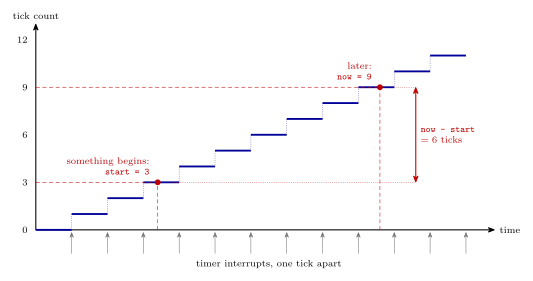
Figure 82: A software timer. The tick count goes up by one at every timer interrupt and never stops. Copying it when something begins gives start, here 3, and reading it again later gives now, here 9. The difference is the time between them in ticks. Any number of start values can be kept at once, which is how a single hardware timer serves every timing job in the program.
The clock in C
A 1 ms tick from timer/counter 0. With the 8 MHz clock divided by 64 the timer counts at 125 kHz, and clearing on a compare match at 124 gives \(8\,000\,000 / (64 \times 125) = 1000\) matches a second.
#include <avr/io.h>
#include <avr/interrupt.h>

volatile uint32_t clock_ticks;            /* milliseconds since reset */

ISR(TIMER0_COMPA_vect) {
    clock_ticks++;
}

void init_clock(void) {
    OCR0A  = 124;                         /* 125 counts per tick           */
    TCCR0A = (1<<WGM01);                  /* clear on compare match (CTC)  */
    TCCR0B = (1<<CS01) | (1<<CS00);       /* clock / 64                    */
    TIMSK0 = (1<<OCIE0A);                 /* enable the interrupt          */
    TIFR0  = (1<<OCF0A);                  /* clear its flag by writing 1   */
}
The handler is as short as a handler can be. The count is volatile because it changes outside the main program’s control (avr-interrupts).
Reading the count safely
The count is 32 bits and the processor is 8-bit, so reading it takes four instructions, one byte each. If the tick interrupt arrives between them, the bytes come from two different values. Going from 0x000000FF to 0x00000100, a read that is interrupted halfway can come out as 0x000001FF or as 0x00000000. Both are wrong by hundreds of ticks.
The cure is to turn interrupts off for the few instructions of the read:
uint32_t get_time(void) {
    uint32_t t;
    uint8_t sreg = SREG;       /* remember whether interrupts were on  */
    cli();                     /* nothing can change the count now     */
    t = clock_ticks;
    SREG = sreg;               /* put the I bit back as it was         */
    return t;
}
Saving SREG and putting it back, instead of calling sei(), means the function is safe to call from anywhere, including from code where interrupts are meant to be off.
The same applies to writing a shared variable of more than one byte from the main program. A single-byte variable needs none of this for a plain read or a plain write, since one instruction does all of it. Changing one in place is different: x++ or flags |= 1 in the main program reads, changes and writes back in separate instructions, and a handler that writes the same variable in between has its change lost. Inside a handler interrupts are already off.
Doing several things at once
With a clock to read, the main loop never waits. On each pass it checks which jobs are due:
void refresh_display(void);                   /* written elsewhere */
void check_buttons(void);

int main(void) {
    uint32_t now, last_blink = 0, last_refresh = 0;

    DDRB |= (1<<0);
    init_clock();
    sei();

    while (1) {
        now = get_time();

        if (now - last_blink >= 500) {        /* every half second */
            last_blink = now;
            PORTB ^= (1<<0);                  /* toggle an LED */
        }

        if (now - last_refresh >= 5) {        /* every 5 ms */
            last_refresh = now;
            refresh_display();                /* show the other digit */
        }

        check_buttons();                      /* every pass: nothing is missed */
    }
}
Each job has its own “last time” variable and its own interval. Adding a job means adding a variable and an if, and no more hardware.
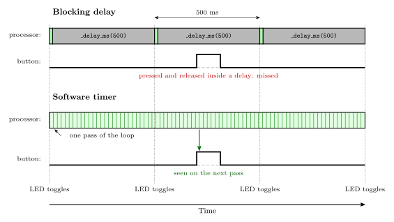
Figure 83: The same job, blinking an LED every half second while also watching a button, written two ways. With a blocking delay the processor is stuck inside the delay almost all the time, and a button press that comes and goes during it is never seen. With a software timer the loop goes round thousands of times a second, looking at the clock and the button on every pass, so the press is caught straight away and the LED still toggles on time.
Measuring a duration
To find how long something took, note the time at the start and subtract at the end:
uint32_t start, held;

start = get_time();                 /* the button went down */
/* ... carry on with the main loop until it comes up ... */
held = get_time() - start;          /* how long it was held, in ms */
A stopwatch that is started once and read later is exactly this. One that can be stopped and restarted keeps a count of its own instead, advanced by the tick handler only while it is running, which is how the stopwatch of week9-lab-avr-interrupts works.
Limits
Resolution. Nothing can be timed more finely than one tick. A duration measured with a 1 ms tick can be out by up to 1 ms, depending on where in a tick it began and ended. A shorter tick is more precise, but the handler runs more often and takes more of the processor’s time.
Wrap-around. The count has a fixed number of bits and eventually goes back to 0.
| Count | Tick | Wraps after |
|---|---|---|
| 16 bits | 10 ms | 655 s, about 11 minutes |
| 16 bits | 1 ms | 65.5 s |
| 32 bits | 1 ms | about 49.7 days |
Unsigned subtraction still gives the right answer across a wrap, as long as the real interval is shorter than one whole trip round. If start was 0xFFFFFFFA and the count is now 0x00000004, then now - start is 10, which is correct. This is why the test is written
if (now - last >= INTERVAL) /* right, even across a wrap */and not
if (now >= last + INTERVAL) /* wrong when last + INTERVAL wraps */This relies on the count being 16 or 32 bits wide. With an 8-bit count C does the subtraction as an int, the wrap is lost, and the result needs a cast: (uint8_t)(now - last).
Common mistakes
- Waiting in a loop for the time to pass.
while (get_time() - start < 500) { }is busy waiting again, only with a better clock. The check belongs in anifinside the main loop, so that everything else keeps running. - Reading a multi-byte count with interrupts on. It works nearly every time and then, rarely, gives a wildly wrong value.
- Forgetting
volatile. The compiler may then read the count once and never look again. - Doing slow work in the tick handler. The handler counts, and may do something quick such as lighting the next display digit. Anything that takes time belongs in the main loop, which decides what is due and does it.
- Comparing with
>=on the sum. Compare the difference with the interval, as above. - Expecting exact intervals. A job runs on the first pass of the loop after it falls due. If another job is slow, this one is late.
See also
- week9-lab-avr-interrupts — Lab 14: a stopwatch on a 10 ms tick
- week9-lab-avr-pwm — Lab 13: where the delay macros are used
- avr-interrupts — handlers in C,
volatile, the I bit - avr-timers-and-counters — CTC mode and the master formula
- polling-and-interrupts — the same trade-off for inputs
- seven-segment-display — display multiplexing, a job that needs regular timing
State Machines
A state machine — equivalently a finite state machine (FSM) — is another name for a sequential circuit, viewed in terms of the states it can be in rather than the gates and flip-flops that implement it. See sequential-circuits for the circuit-level view and flip-flops-and-latches for the storage elements the state lives in.
What a state machine is
A state machine has:
- a finite number of possible states — \(N\) flip-flops give at most \(2^N\) of them;
- only one current state at any moment;
- the ability to transition to other states, based on the inputs and the current state.
The state is exactly the value held in the flip-flops (see sequential-circuits), so the flip-flop count bounds the state count. It does not fix it: how many flip-flops a given number of states actually costs is an encoding choice, made at the state-encoding step below.
Naming the two blocks of logic
The standard sequential-circuit structure has one combinational block computing two different things, and it is worth naming them separately:
\[\text{OUT} = g(\text{IN}, Q) \qquad\qquad D = f(\text{IN}, Q)\]
- \(Q\) is the present state (PS) — what the flip-flops hold right now.
- \(D\) is the next state (NS) — what they will hold after the next clock edge.
- \(g\) is the output logic; \(f\) is the transition logic (also called next-state logic).
Designing an FSM comes down to finding Boolean expressions for \(f\) and \(g\).
Defining the states from the problem
States are not handed to you — they come from the problem, and the useful question is what does the circuit need to remember?
Vending machine. A machine accepts 5c and 10c coins and dispenses a candy when it has received 15 cents in total. What are the states?
What the machine must remember is the running total inserted so far:
| Total inserted | 0 | 5 | 10 | 15 | 20 | 50 |
|---|---|---|---|---|---|---|
| Dispense candy? | no | no | no | yes | yes, plus change | — |
So the states are the totals 0, 5 and 10, with 15 and 20 being the ones that dispense (20 arises from inserting 10c on top of 10c, and needs change). A total of 50 is not a state at all: with only 5c and 10c coins the machine dispenses and resets long before it could get there, so it is unreachable.
Moore and Mealy machines
There are two types, differing only in what the output logic is allowed to see:
- Mealy machine — outputs depend on the current state and the inputs.
- Moore machine — outputs depend only on the current state (the flip-flop values). Consequently, outputs can only change when the state changes.
A Moore machine is a special case of a Mealy machine — the one where the output logic simply ignores its input connections. CSSE2010 sticks to Moore machines.
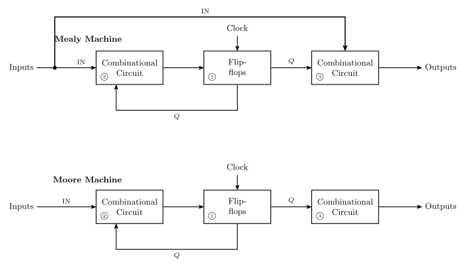
Figure 84: Mealy (top) and Moore (bottom). ① is the state, held in the flip-flops; ② is the transition logic; ③ is the output logic. The only structural difference is the branch drawn in bold: in a Mealy machine the inputs reach the output logic directly, so the outputs are a function of IN and Q; in a Moore machine the output logic sees Q alone.
State diagram notation
A state diagram draws the states as circles and the transitions as labelled arrows.
States are drawn as a circle split in two: the state name on top, the output value(s) underneath. So \(S_0\) over \(101\) is a state called \(S_0\) whose outputs are 101; the name is arbitrary and need not be \(S_n\) (a state called Alex over \(01\) is just as legal).
Transitions are arrows labelled with a logic expression over the inputs — if the expression is true, that transition is taken. Examples of labels: \(Z\), \(\overline{\text{RESET}}\), \(A + B\cdot\overline{C}\).
Two conventions worth knowing:
- No label means “true” — the transition is always taken on the next clock edge. This is what the arrows in a plain counter’s diagram look like.
- With only one input, the label may be written as just
0or1instead of a Boolean expression. This is a special case of the general form; \(1\) means the same as \(Z\) and \(0\) the same as \(\overline{Z}\).
Completeness
Each possible combination of inputs should be addressed exactly once for each state.
That is, the transition arrows leaving each state must encompass all possibilities, without overlap and without gaps. With \(N\) inputs there are \(2^N\) input combinations, so every state needs \(2^N\) transitions accounted for — though several combinations leading to the same next state can be merged onto one arrow with an OR’d label.
This is a checkable property, and checking it is the cheapest way to catch a half-finished design: if the labels on the arrows out of a state do not OR together to 1, some input combination has no defined behaviour; if any two of them can be true at once, the machine is ambiguous.
A counter is a state machine with no inputs
The design method for counters — write the sequence as a present-state/next-state table, read each \(D\) column off as a Boolean function of the \(Q\)’s, draw the gates — is steps 3, 5 and 6 of the pipeline below, applied to the degenerate case where the machine has no external inputs at all. A counter may or may not have external inputs.
Three things collapse when \(\text{IN}\) is empty:
- Transition logic. \(D = f(\text{IN}, Q)\) becomes \(D = f(Q)\), so the state table needs no input column and the excitation equations are functions of the \(Q\)’s alone.
- Output logic. A counter’s output is its state, so \(g\) is the identity and there is no second block of gates. That also makes every counter trivially a Moore machine.
- Completeness. With \(N = 0\) inputs there are \(2^0 = 1\) input combinations, so the completeness rule reduces to exactly one arrow out of each state — and by the “no label means true” convention, that arrow is unlabelled.
The state encoding step also disappears, or rather it is made for you: the states of a counter are already bit patterns, and the sequence you were given is the encoding.
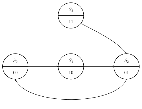
Figure 85: The 2-bit counter for \(00 \to 10 \to 01 \to 00\) drawn as a state diagram. Every arrow is unlabelled because the machine has no inputs, so each transition is taken unconditionally on the next clock edge; each state’s output half carries the count value, since a counter’s output is its state. \(S_3\) is the unused state: three states cannot fill a two-flip-flop machine, so its next state is a don’t-care, and choosing \(11 \to 01\) for it is what makes the design self-correcting.
Figure 85 read as a state table, with the unused row carrying the don’t-cares:
| Current state | Next state | \(Q_1\) | \(Q_0\) |
|---|---|---|---|
| \(S_0\) | \(S_1\) | 0 | 0 |
| \(S_1\) | \(S_2\) | 1 | 0 |
| \(S_2\) | \(S_0\) | 0 | 1 |
| \(S_3\) | (don’t care) | 1 | 1 |
The unused state is where the FSM framing pays for itself. A don’t-care is a free choice of transition, not an absence of one: the circuit will do something in state \(S_3\), and the only question is whether the arrow you have implicitly drawn leads back into the cycle or loops onto itself. An arrow from \(S_3\) to itself is a trap state — the machine leaves the intended cycle and never returns. There are two candidate simplifications for \(D_1\). The tidier one, \(D_1 = \overline{Q_1 \oplus Q_0}\), puts a self-loop on \(S_3\) and is rejected. The other sends \(11 \to 01\), back into the cycle, and is the robust design. See counters and 2026-08-17-counters for that working.
State tables
The same information as a state diagram, in tabular form. Two layouts, both in use.
One-dimensional — one row for every combination of state and inputs:
| Current State | Input \(U\) | Next State | \(Q_1\) | \(Q_0\) |
|---|---|---|---|---|
| \(S_0\) | 0 | \(S_3\) | 0 | 0 |
| \(S_0\) | 1 | \(S_1\) | 0 | 0 |
| \(S_1\) | 0 | \(S_0\) | 0 | 1 |
| \(S_1\) | 1 | \(S_2\) | 0 | 1 |
| \(S_2\) | 0 | \(S_1\) | 1 | 0 |
| \(S_2\) | 1 | \(S_3\) | 1 | 0 |
| \(S_3\) | 0 | \(S_2\) | 1 | 1 |
| \(S_3\) | 1 | \(S_0\) | 1 | 1 |
Two-dimensional — one row per state, with a next-state column for every combination of inputs:
| Current State | Next State (\(\overline{U}\)) | Next State (\(U\)) | \(Q_1\) | \(Q_0\) |
|---|---|---|---|---|
| \(S_0\) | \(S_3\) | \(S_1\) | 0 | 0 |
| \(S_1\) | \(S_0\) | \(S_2\) | 0 | 1 |
| \(S_2\) | \(S_1\) | \(S_3\) | 1 | 0 |
| \(S_3\) | \(S_2\) | \(S_0\) | 1 | 1 |
Both describe the same machine (a 2-bit up/down counter, \(U = 1\) counts up). The 2D form is more compact and makes completeness visually obvious — every input combination is a column, so a missing case is a missing column. The 1D form grows as \(2^N \times\) (number of states) but maps directly onto a truth table, which is what the next design step needs. In a Moore machine the output columns depend only on the current state, which is why they can sit in a per-state row at all.
State encoding
Each state must be encoded into flip-flop values before the design can become a circuit. Two choices to make:
- the number of flip-flops, and
- the bit patterns representing each state.
Ideally, choose the encoding that makes the combinational logic simple — for both the output logic and the next-state logic. Different encodings of the same machine give genuinely different gate counts.
Three common schemes, on a four-state machine:
| State | Binary | Gray | One-hot |
|---|---|---|---|
| \(S_0\) | 00 | 00 | 0001 |
| \(S_1\) | 01 | 01 | 0010 |
| \(S_2\) | 10 | 11 | 0100 |
| \(S_3\) | 11 | 10 | 1000 |
- Binary — the obvious count; \(\lceil \log_2 n \rceil\) flip-flops for \(n\) states.
- Gray — same width, but consecutive states differ in exactly one bit (see binary-number-representations).
- One-hot — one flip-flop per state, with only one flip-flop holding 1 at any time. Far more flip-flops, but the next-state and output logic often collapses to almost nothing, since “am I in state \(S_k\)” is just a single flip-flop’s output rather than a decoded combination.
Steps involved in FSM design
- Defining state based on the problem definition.
- Drawing the state diagram.
- Completing the state table (1D or 2D).
- State encoding, and re-doing the state table with encoded states.
- Obtaining the Boolean expressions for the next-state logic (i.e. the \(D\)’s) and for the outputs.
- Drawing the logic diagram.
- Simulating in Logisim to verify functionality.
- Building and testing the circuit in hardware.
Steps 1–6 are the pen-and-paper design; steps 7–8 are what the learning labs do with it. Steps 5 and 6 are the same techniques used to build a counter by hand — see counters and circuit-schematics.
See also
- sequential-circuits · flip-flops-and-latches · counters · shift-registers
- 2026-08-17-counters — Lecture 7, where this design method is first used (on counters)
- 2026-08-20-state-machines — Lecture 8
- week9-lab-avr-interrupts — Lab 14: a stopwatch controller designed as a Moore machine and written in C
Comments and directives
Comments start with semicolons. Everything from a
;to the end of the line is ignored by the assembler..include "m324Adef.inc"is an assembler directive, not an instruction — nothing is generated for it. The contents of the file are included directly in the program, which is what makesDDRA,PORTC,TCNT0and the rest usable as names instead of I/O register numbers (see avr-io-ports). The leading dot is the giveaway: a line starting.speaks to the assembler, a line starting with a mnemonic speaks to the CPU.Every line has the same shape, with up to four fields: a label, an operation, its operands and a comment, as in
loop: jmp loop ; Repeat. The operation is either an instruction or, with the leading dot, a directive. Two more directives turn up in most programs:.def temp = r16gives a register a name, and.equgives a number a name. The fields, and every directive with what it does, are in assembly-process.