Lecture 20 — Assembly Process
Assembly language is more than instructions, and turning it into machine code takes more than translating one line at a time. This covers the four fields of a statement, the directives that speak to the assembler instead of the CPU, the AVR’s three memory segments, and the two-pass assembler that gets round the forward reference problem. Two programs are traced to find the address every label is given. The reference note is assembly-process. The program skeleton it all fits into is avr-program-structure, and the memories behind the segments are in memory-models.
Goals
- See that an assembly program holds more than instructions: directives tell the assembler where things go and what names mean.
- Know the AVR’s memory segments and which directives put what in each.
- Understand how an assembly program becomes machine code, and why the assembler reads the source twice.
- Be able to work out by hand the address each label is given.
Where assembly sits
The six levels of a computer are in 2026-07-27-course-intro-bits-bytes-binary. There are two roads down to machine code:
- a C program, at the problem-oriented language level, is compiled, and one line can become many instructions (2026-09-07-introduction-to-embedded-c-programming; the rest of that road is 2026-10-15-compilation-and-linking);
- an assembly program, one level down, is assembled, each instruction to exactly one machine instruction.
Each instruction on its own has a fixed binary form, its machine code (avr-instructions). That leaves two questions: what else goes in an assembly program, and how does the assembler turn a whole program into machine code?
The four fields of a statement
A statement has four parts, called fields:
formula: ldi r20, i ; register r20 = i| Field | Here | What it is |
|---|---|---|
| label | formula: |
a name for the address this statement lands at |
| operation (opcode) | ldi |
the mnemonic |
| operand(s) | r20, i |
what the operation works on |
| comment | ; register r20 = i |
explanation, ignored by the assembler |
The fields are drawn one by one in assembly-process.
- Labels are needed so that statements can be jumped to, and so that data can be referred to. The label’s value is an address:
formulais the address of thatldi. A label usually starts in column 1, with everything else indented. - The operation is a symbolic abbreviation for the opcode, for example
LDS, Load Direct from data Space. - The operand field gives the addresses and registers the instruction uses. Register names vary from machine to machine: the Pentium has
eax,ebx,esi,ediand so on; SPARC haso0..o7,i0..i7,l0..l7andg0..g7; the AVR simply hasr0..r31. - The comment is for people only, and in assembly it is vital: the instructions say what happens, never why.
- Some assemblers require a semicolon to end each statement and some do not. The AVR’s does not, and there a semicolon begins a comment.
Directives
The assembler needs information that is not an instruction:
- where in memory the program and its data should go;
- nicer names to use for registers and addresses, such as
temporSPH.
That information is a command to the assembler itself, a pseudo-instruction or directive. Directives are preceded by a dot: .byte reserves space for a variable, and .def temp = r16 lets the program say temp for register r16.
Memory segments
To the assembler, the different types of memory are segments, and directives choose which segment code and data go into. The AVR has three:
| Segment | Directive | Memory | What goes there |
|---|---|---|---|
| data | .dseg |
RAM (SRAM) | nothing can be placed: only space reserved, for variables |
| code | .cseg |
flash | program code or constant data |
| EEPROM | .eseg |
EEPROM | constants |
One source file can switch between segments as often as it likes. Each piece goes to its own memory, and pieces of the same segment are joined end to end, as Figure 1 below shows for data and assembly-process shows for all three.
The directives
The assembler in Microchip Studio (formerly Atmel Studio) is AVRASM2. It has these directives, among others:
| Kind | Directives |
|---|---|
| choosing a segment | .cseg code, .dseg data, .eseg EEPROM; .csegsize sets the program memory size |
| reserving and defining data | .byte reserves bytes for a variable; .db defines constant bytes; .dw defines constant words |
| naming | .def gives a register a symbolic name; .equ sets a symbol to an expression; .set does the same but can be changed |
| placing | .org sets the program origin, the location counter |
| files | .include reads source from another file; .exit stops reading this one |
| list file | .list and .nolist turn list-file generation on and off; .listmac shows macro expansions in it |
| macros | .macro begins one; .endm or .endmacro ends it |
| conditional assembly | .if opens a block that is assembled only when its condition holds; .else, .elif and .endif continue and close it |
Each is described in assembly-process.
Reserving space and defining constants
.byte reserves space, and it is allowed only in the data segment.
.cseg and .dseg let the code and data segments be built up in pieces: switching back to a segment carries on where it left off.
Worked: a data segment built in pieces
Where do amount and count go?
        .dseg
amount: .byte 2
        .cseg
formula: ...
        .dseg
count:  .byte 2
The data counter starts at 0x0100 (256), the first SRAM address after the 32 registers, the 64 I/O registers and the 160 extended I/O registers.
.dseg: use the data counter, at0x0100.amount=0x0100..byte 2reserves0x0100and0x0101; the counter moves to0x0102..cseg:formulaand whatever follows it go to program memory, under the code counter. The data counter is left alone at0x0102..dseg: back to the data counter, still0x0102.count=0x0102(258). It reserves0x0102and0x0103, and the counter ends at0x0104.
So count sits immediately after amount in SRAM, although the code for formula lies between them in the file.
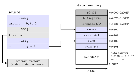
Figure 1: A data segment built in two pieces. The data counter starts at 0x0100, just past the registers and the I/O registers, so amount gets the two bytes there. The code in the middle of the file goes to program memory under the code counter and does not move the data counter, so when the file returns to the data segment count takes the next two bytes, 0x0102 and 0x0103. Nothing is written into these bytes: the assembler only gives out addresses, and the rest of SRAM up to 0x08FF stays free. Blue marks the data segment and grey the code segment.
.db initialises constants in the code or EEPROM segment, 8 bits each. .dw does the same with 16-bit words. Program memory is 16 bits wide, so .db bytes go two to a word, and an odd count is padded with a zero byte.
Worked: a lookup table
Where do the three tables go, and what is in each word?
        .cseg
table1: .db  11, 12, 30
table2: .dw  100, 133
        .org 500
table3: .dw  ...
With the code counter at 0:
table1= 0. Word 0 holds 11 and 12; word 1 holds 30 and a pad 0. The counter moves to 2. Writing the pad as a fourth value,.db 11, 12, 30, 0, gives exactly the same two words, without the assembler’s padding warning.table2= 2. Word 2 is 100 and word 3 is 133. The counter moves to 4..org 500sets the counter to 500, skipping words 4 to 499.table3= 500.
The layout is drawn in assembly-process.
Registers, devices and files
.defmakes a definition, for registers only:.def ZH=r31 .def ZL=r30.devicesays exactly which processor the program is for, as in.device ATmega324A. The assembler then refuses any instruction that chip does not implement..includeincludes another file at that point, as.include "m324Adef.inc"does in every program so far (avr-program-structure)..exitstops processing the file.
Symbols and the location counter
.equequates a symbol to a value, and the value cannot be changed..setequates too, but the value can be changed by a later.set..equ sreg = 0x3f ; Status register .set io_offset = 0x23 ; For nowsregis fixed for the whole file.io_offsetis 0x23 for now: a later.set io_offset = ...replaces it from that line on..orgsets the location counter, the address the next item will be placed at, in whichever segment is current.
All of these are the syntax of the assembler built into Microchip Studio. Other assemblers, even ones for the AVR, use different syntax: avr-gcc’s assembler reads .byte as “store these bytes”, not “reserve this many”.
The forward reference problem
An assembly program is a sequence of one-line statements, but the assembler cannot always read a statement and produce its machine code on the spot. add r1, r2 is fine: the opcode and both registers are known, so the word can be written immediately. A program’s first statement is usually
jmp RESETand the RESET: label is further down. At the jmp, the assembler knows the opcode but not the operand: it has no address for RESET, so it cannot generate the instruction. This is the forward reference problem.
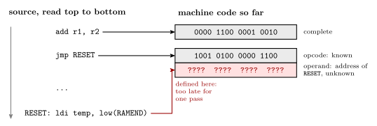
Figure 2: Why a single pass from top to bottom is not enough. The add names only registers, so its machine word is complete the moment the line is read. The jmp is two words: the first holds the opcode and can be written, but the second must hold the address of RESET, and RESET is defined further down. By the time the assembler reaches that definition and learns the address, the jmp is already behind it. Red marks the word that cannot be filled in yet and the line that supplies its value.
Two passes
The solution is to process the file twice.
- Pass one defines all the symbols: labels, and the names made by
.equ,.setand.def. It keeps a location counter for each segment and records every symbol’s value in a symbol table. It does not need any operand to do this, only each statement’s size. - Pass two starts again from the top. The values of all the symbols are now known, so it can assemble each instruction, which means producing the actual machine code.
The pipeline is drawn in assembly-process.
Worked: the two-pass example
At what program address will the instruction at label RESET be placed, and what are the other symbols’ values?
        .equ    RAMEND = $08FF
        .equ    SPH = $3E
        .equ    SPL = $3D
        .def    ZH = r31
        .def    ZL = r30
        jmp     RESET
        .dseg
var1:   .byte   2
var2:   .byte   2
        .cseg
        .def    temp = r16
mesg:   .db     72,101,108,108,111
table:  .dw     var1, var2
RESET:  ldi     temp, low(RAMEND)
        out     SPL, temp
        ldi     temp, high(RAMEND)
        out     SPH, temp
        ...
        ldi     ZH, high(mesg*2)
        ldi     ZL, low(mesg*2)
        lpm                     ;R0 <= M[Z]
Pass one, one line at a time. Code counter from 0 (in words), data counter from 256, 0x0100 (in bytes), EEPROM counter not used.
| Line | Segment | Placed at | Size | Counter after | Symbol table gains |
|---|---|---|---|---|---|
.equ RAMEND = $08FF |
0 | RAMEND = 0x08FF |
|||
.equ SPH = $3E |
0 | SPH = 0x3E |
|||
.equ SPL = $3D |
0 | SPL = 0x3D |
|||
.def ZH = r31 |
0 | ZH = r31 |
|||
.def ZL = r30 |
0 | ZL = r30 |
|||
jmp RESET |
code | 0, 1 | 2 words | code 2 | |
.dseg |
data | 0 | data 256 | ||
var1: .byte 2 |
data | 256, 257 | 2 bytes | data 258 | var1 = 256 |
var2: .byte 2 |
data | 258, 259 | 2 bytes | data 260 | var2 = 258 |
.cseg |
code | 0 | code 2 | ||
.def temp = r16 |
0 | temp = r16 |
|||
mesg: .db 72,101,108,108,111 |
code | 2, 3, 4 | 5 bytes + pad = 3 words | code 5 | mesg = 2 |
table: .dw var1, var2 |
code | 5, 6 | 2 words | code 7 | table = 5 |
RESET: ldi temp, low(RAMEND) |
code | 7 | 1 word | code 8 | RESET = 7 |
out SPL, temp |
code | 8 | 1 word | code 9 | |
ldi temp, high(RAMEND) |
code | 9 | 1 word | code 10 | |
out SPH, temp |
code | 10 | 1 word | code 11 |
The data counter runs 256, 258, 260, and the code counter 0, 2, 5, 7 and on.
The instruction at RESET is at program address 7. The full table, and the trace drawn line by line, are in assembly-process.
| Symbol | Segment | Value |
|---|---|---|
RAMEND |
0x08FF |
|
SPH |
0x3E |
|
SPL |
0x3D |
|
ZH |
r31 |
|
ZL |
r30 |
|
RESET |
code | 7 |
var1 |
data | 256 |
var2 |
data | 258 |
temp |
r16 |
|
mesg |
code | 2 |
table |
code | 5 |
RESET can go in the table the moment the jmp mentions it, with its value left blank until RESET: turns up; the finished table is the same either way.
Pass two fills in every operand:
jmp RESETbecomesjmp 7, two words0x940C 0x0007..dw var1, var2writes the two data addresses, 256 and 258 (0x0100and0x0102), into words 5 and 6.ldi temp, low(RAMEND)becomesldi r16, 0xFFandldi temp, high(RAMEND)becomesldi r16, 0x08. With the twoouts toSPLandSPH(I/O addresses0x3Dand0x3E), they set the stack pointer to the top of SRAM (procedures-and-the-stack).mesg*2= 4, soldi ZH, high(mesg*2)loads 0 andldi ZL, low(mesg*2)loads 4.mesgis word 2, which starts at byte 4, andlpmwants a byte address in Z. It loadsr0with the byte there: 72, theHofHello(memory-models).
Every encoded word is listed in assembly-process.
Worked: where does RESET land?
At what program address will the instruction at label RESET be placed?
        jmp RESET
        jmp ISR1
        jmp ISR2
.dseg
var1: .BYTE 1
var2: .BYTE 3
var3: .BYTE 2
.cseg
.def temp=r20
message1: .DB 72,101,111,111,0
message2: .DB 0,65,66,68,0
RESET:
        ldi temp, low(RAMEND)
        out SPL, temp
        ldi temp, high(RAMEND)
out SPH, temp- A. 9
- B. 12
- C. 15
- D. 18
- E. None of the above
B, 12. Follow the code counter only:
- Three
jmps at 2 words each: addresses 0, 2 and 4. The counter is at 6. - The
.dsegblock moves the data counter:var1=0x0100,var2=0x0101,var3=0x0104, ending at0x0106. The code counter does not move. .csegreturns to the code counter, still 6..deftakes no space.message1: 5 bytes, padded to 6, is 3 words: 6, 7 and 8. The counter is at 9.message2: another 5 bytes, padded to 6, so 3 words: 9, 10 and 11. The counter is at 12.RESET:labels the next instruction: 12.
\[\underbrace{3 \times 2}_{\texttt{jmp}} + \underbrace{3}_{\texttt{message1}} + \underbrace{3}_{\texttt{message2}} = 12\]
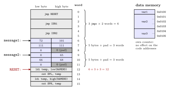
Figure 3: Program memory for the question, one 16-bit word per row, lowest address at the top. Each jmp takes two words, the opcode and the target address. Each .DB line of five bytes fills two and a half words, and the assembler pads the last half with a zero so the next line starts on a whole word. That puts message1 at 6, message2 at 9 and RESET at 12. The variables are in data memory under their own counter, so they take no program memory at all. Light grey marks instructions, blue the .DB bytes and the variables, and dark grey the pad bytes.
Each wrong answer matches a slip worth recognising:
- A, 9, counts each
jmpas one word: \(3 + 3 + 3\). - C, 15, lets the six bytes of variables into the code counter as three words: \(6 + 3 + 3 + 3\). The
.dseglines have their own counter and take no program memory. - D, 18, makes the same mistake with the six bytes as six words, \(6 + 6 + 3 + 3\), or gives every
.DBbyte a word of its own, \(6 + 6 + 6\) with the pads. - E would be right if the two strings were packed together with no padding between them, \(6 + 5 = 11\). The assembler pads each
.DBline separately.
See also
- assembly-process — the reference note: statement fields, every directive, segments and location counters, the two-pass assembler with figures, and the encoded output of the example
- avr-program-structure — the program skeleton, now with its directives and segments
- memory-models — word addresses against byte addresses, and the AVR’s separate address spaces
- avr-branches-and-jumps — why
jmpis two words andrjmpone - avr-interrupts — the vector table that the three
jmps at the top belong to - procedures-and-the-stack — the stack-pointer set-up after
RESET: - 2026-10-05-more-io — Lecture 19
- 2026-10-15-compilation-and-linking — Lecture 22: the road from C