AVR Instructions
The AVR instructions introduced so far, in assembly and in machine code. See instruction-set-architecture for what an instruction set is and avr-architecture for the hardware that runs these.
The full alphabetical instruction set — each mnemonic with its operation, description, flags affected, clock count, opcode pattern and an example — is in the AVR instruction set reference: Atmel’s AVR Instruction Set Manual, and the instruction summary in the ATmega324A datasheet the course says to keep open. The notation key immediately below and the per-instruction flag table at the end are unverified against that reference — check them against your own copy before leaning on them.
Reading the instruction set reference
Operand notation — how an operand’s allowed values map onto opcode bits:
| Notation | Meaning | Values | Opcode pattern |
|---|---|---|---|
Rd |
destination register (may be a source too) | r0…r31 | ddddd |
| r16…r31 | dddd (register number − 16) |
||
Rr |
source register | r0…r31 | rrrrr |
Rh:Rl |
register pair as a 16-bit quantity | r25:r24 / X / Y / Z | dd (00 / 01 / 10 / 11) |
K |
constant data | 0…255 | KKKKKKKK |
k |
constant address | −64…63, −2048…2047, 0…65535 | kkkkkkk … kkkk kkkk kkkk kkkk |
b |
bit number in a register | 0…7 | bbb |
s |
bit in the status register | 0…7 | sss |
P |
I/O register number | 0…63 | PPPPPP |
q |
displacement for direct addressing | 0…63 | qqqqqq |
The Rd row is the whole story behind LDI’s restriction — an instruction spending five bits on the register gets all 32; one spending four gets sixteen, and pays for it by starting at r16.
Operation notation — used in the Operation column:
M[a] / PM[a] / IO[a] |
SRAM cell / program memory (flash) byte / I/O register at address a |
PC / SP / STACK |
program counter / stack pointer / M[SP] |
← |
assigned value |
reg(a) |
bit a of register reg, numbered 7…0 most to least significant |
Flag names in the Flags Affected column are the SREG bits of avr-architecture.
Register conventions
Two operand names recur throughout the instruction set:
rd— the destination register.rr— the source register.
AVR is a two-operand machine: the destination is also one of the sources, so add rd, rr means rd ← rd + rr. (Contrast a three-operand ISA such as ARM, where add rd, r1, r2 leaves both sources untouched.) This matters when reading code — an AVR arithmetic instruction always overwrites one of its inputs.
Instructions by type
The instruction set can be cut two ways.
By what the instruction touches — the instruction-type list of instruction-set-architecture, filled in with the instructions so far:
| Type | Does | AVR so far |
|---|---|---|
| Input/Output | communicate with I/O devices/ports | IN, OUT |
| Load/Store | move data from/to memory | LD, LDS, ST, STS |
| Move | copy data between registers | MOV |
| Arithmetic | addition, subtraction, … | ADD, ADC, SUB, INC, NEG |
| Logical | Boolean operations | AND, ANDI, OR, ORI, EOR, COM |
| Branching | deciding which instruction to perform next | JMP, BREQ, BRNE |
By operand count, which splits the arithmetic and logical group instead:
| AVR examples | ||
|---|---|---|
| Dyadic | combine 2 operands to produce a result | add r5, r6 (arithmetic) · and r5, r6 (logical, bitwise) |
| Monadic | one operand → one result | ser r16 (set) · clr r5 (clear) · neg r5 (2’s complement) · com r5 (1’s complement) · the shifts and rotates |
The second cut is the one that predicts the syntax: a dyadic instruction has a comma in it, a monadic one does not.
The instructions so far
| Instruction | Meaning | Example |
|---|---|---|
MOV rd, rr |
copy contents of rr into rd — rd ← rr |
mov r3, r14 |
ADD rd, rr |
add contents of rr to rd — rd ← rd + rr |
add r5, r6 |
ADC rd, rr |
add with carry — rd ← rd + rr + C |
adc r11, r5 |
AND rd, rr |
bitwise AND, result into rd |
|
OR rd, rr |
bitwise OR, result into rd |
|
EOR rd, rr |
bitwise exclusive-OR, result into rd |
|
INC rd |
rd ← rd + 1 |
inc r22 |
LDI rd, number |
load immediate — put the number into rd |
ldi r16, 73 |
SER rd |
set all bits — rd ← $FF. Same as ldi rd, 0xFF, so r16–r31 only |
ser r17 |
CLR rd |
clear all bits — rd ← 0. Same as eor rd, rd, so any register |
clr r3 |
SUB rd, rr |
rd ← rd − rr |
sub r7, r19 |
COM rd |
one’s complement — flip all bits | com r8 |
NEG rd |
two’s complement — negate | neg r9 |
ANDI rd, K |
bitwise AND with a constant — r16–r31 only | andi r16, 0x01 |
ORI rd, K |
bitwise OR with a constant — r16–r31 only | ori r16, 0xF0 |
MOV is named misleadingly: it copies, it does not move. The source register is unchanged. It also affects no flags, which is what makes it safe to shuffle values between operations without disturbing the status register.
SER and CLR are short-hand ways of setting/clearing all bits of a register, and their restrictions differ because their expansions do:
| Exactly the same as | Reaches | |
|---|---|---|
ser rd (set register) |
ldi rd, 0xFF |
r16–r31 only — it inherits LDI’s four-bit register field |
clr rd (clear register) |
eor rd, rd |
any register, r0–r31 — EOR is a two-register instruction with five bits for each |
So clr r3 is legal and ser r3 is not, which looks arbitrary until you look at what each one assembles to. clr is also the reason \(X \oplus X = 0\) from bit-masking is worth remembering: XORing a register with itself is how the machine zeroes one.
Compare instructions
These do the arithmetic, discard the result, and keep only the flags — which is exactly what a conditional branch needs.
| Instruction | Does | Note |
|---|---|---|
CP rd, rr |
rd − rr |
compares two registers |
CPI rd, K |
rd − K |
compares against a constant — like ldi, r16–r31 only |
TST rd |
rd AND rd |
examines one register; literally the same operation as and rd, rd |
tst looks odd until you notice that ANDing a value with itself leaves it unchanged (\(X \cdot X = X\)) but still sets N and Z from it — so it is a zero/sign test that costs nothing and clobbers nothing. See bit-masking.
A comparison is the same as subtraction, with the result not saved — it exists only to set status register flags (Z, N, C, V …). And the instruction reference specifies which status register bits are set by which instructions: the flags are defined per instruction rather than falling out of one shared adder, which is the point of the table at the end of this note.
Branch instructions
Based on status register values — the flags a compare just set:
Branches to label if |
|
|---|---|
BREQ label |
Z = 1 |
BRNE label |
Z = 0 |
Together with CP that is a complete conditional: compare, which sets Z exactly when the two operands were equal, then branch on Z.
    cp   r5, r6          ; r5 - r6, result thrown away, flags kept
    breq same            ; Z = 1, i.e. r5 == r6
JMP label is the unconditional version — it tests nothing and always goes. Labels, and the program skeleton the branches live in, are in avr-program-structure.
breq/brne are two of ten: there is one branch per status flag per value, and the pairs that matter for ordering are brsh/brlo (unsigned, on C) and brge/brlt (signed, on S) — the full table, and why the signed pair reads S rather than N, are in avr-branches-and-jumps.
Control flow
The instructions that write the PC, and the two stack instructions that go with the calls (avr-branches-and-jumps, procedures-and-the-stack):
| Instruction | Does | Words | Cycles |
|---|---|---|---|
BRxx label |
branch if a flag has the wanted value; reach ±64 words | 1 | 1 (not taken) / 2 (taken) |
JMP label |
PC ← address of label |
2 | 3 |
RJMP label |
PC ← PC + offset; reach ±2 K words | 1 | 2 |
IJMP |
PC ← Z | 1 | 2 |
CALL label |
push the return address, then as JMP |
2 | 4 |
RCALL label |
push the return address, then as RJMP |
1 | 3 |
ICALL |
push the return address, then as IJMP |
1 | 3 |
RET |
pop the return address into PC | 1 | 4 |
PUSH rr |
store rr at SP, SP ← SP − 1 |
1 | 2 |
POP rd |
SP ← SP + 1, load rd from SP |
1 | 2 |
None of these touches the status register except by what the pushed and popped values happen to be; a call between a cp and its branch is safe only if the procedure preserves the flags, which in practice means it is not.
Three more belong to interrupts, and between them they are the only instructions that change the I bit (avr-interrupts):
| Instruction | Does | Words | Cycles |
|---|---|---|---|
SEI |
I ← 1: interrupts enabled | 1 | 1 |
CLI |
I ← 0: interrupts disabled | 1 | 1 |
RETI |
pop the return address into PC, and I ← 1 | 1 | 4 |
RETI is RET plus set I. A handler that ends in RET returns to the right place and leaves interrupts off for good.
Data movement
Data is usually copied, not moved — in every instruction below the source is left alone. What changes is where the two ends are:
| Direction | Called | AVR |
|---|---|---|
| register → register | move | mov |
| memory → register | load | lds, ld |
| register → memory | store | sts, st |
| I/O register → register | input | in |
| register → I/O register | output | out |
Three different places a value can live — a general purpose register, data memory, an I/O register — and a different instruction family for each. The one thing that is genuinely out of reach is SRAM from in/out: P only goes up to 0x3F, so those two never leave the first 64 I/O registers.
Everything else is a question of cost and numbering, not reachability. Because the I/O registers are mapped into the data space (avr-io-ports), lds/sts can reach one — in r16, 0x09 and lds r16, 0x29 both read PIND, the second for two instruction words instead of one. The bug to actually watch for is writing the I/O register number where the data address belongs, or the reverse.
Load and store
| Does | Addressing | Words | Cycles | |
|---|---|---|---|---|
LD rd, X |
rd ← Mem[X] |
indirect — address in the pointer register | 1 | 2 |
ST X, rr |
Mem[X] ← rr |
indirect | 1 | 2 |
LDS rd, k |
rd ← Mem[k] |
direct — 16-bit address in the instruction | 2 (32 bits) | 2 |
STS k, rr |
Mem[k] ← rr |
direct | 2 | 2 |
For example:
    ld   r5, X           ; r5 <- Mem[X]
    st   X, r5           ; Mem[X] <- r5
    lds  r5, 0x20        ; r5 <- Mem[0x20]
    sts  0x20, r5        ; Mem[0x20] <- r5
Both pairs reach the same data space — the difference is only where the address comes from (addressing-modes), and lds/sts pay a second instruction word for spelling it out. X here is the pointer pair of avr-architecture.
In and out
| Does | Words | Cycles | |
|---|---|---|---|
IN rd, P |
rd ← I/O register P |
1 | 1 |
OUT P, rr |
I/O register P ← rr |
1 | 1 |
rd/rr may be any of r0–r31 — unlike ldi, these are not restricted to the top half — and P is an I/O register number 0–63 (0x00–0x3F) or a name from m324Adef.inc. Examples: in r5, 0x26 (I/O register 0x26 is TCNT0) and out PORTD, r6. Full treatment in avr-io-ports.
One word and one cycle makes these the cheapest access on the chip — cheaper than reaching the very same register through lds/sts, which is the whole reason the first 64 I/O registers are special.
Shifts and rotates
Monadic instructions that move every bit one place. They differ only in what arrives at the vacated end and what happens to the bit that falls off — and in all five, the bit that falls off lands in C.
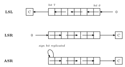
Figure 1: The three shift instructions. LSL and LSR feed a 0 into the vacated end; ASR feeds the sign bit back into itself, which is what makes it a signed division. In all three the bit shifted out lands in the carry flag.
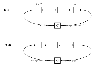
Figure 2: The two rotate instructions. A rotate is a shift whose vacated end is fed from the carry flag instead of a constant, so the register and C together behave as a nine-bit ring.
| Name | Into the vacated end | Out | |
|---|---|---|---|
LSL rd |
Logical Shift Left | 0 → bit 0 |
bit 7 → C |
LSR rd |
Logical Shift Right | 0 → bit 7 |
bit 0 → C |
ASR rd |
Arithmetic Shift Right | bit 7 replicated into itself | bit 0 → C |
ROL rd |
ROtate Left through carry | C → bit 0 | bit 7 → C |
ROR rd |
ROtate Right through carry | C → bit 7 | bit 0 → C |
What they compute
Shifting a binary number one place is multiplying or dividing it by two, which is the whole reason these exist. Using four bits for legibility:
| Worked example | ||
|---|---|---|
LSL |
× 2 | 0010 (2) → 0100 (4) → 1000 (8) |
LSR |
÷ 2, read unsigned | 0110 (6) → 0011 (3); 1000 (8 unsigned) → 0100 (4) |
ASR |
÷ 2, read signed | 1000 (\(-8\)) → 1100 (\(-4\)) |
LSR and ASR are the pair to keep straight. Given 1000, LSR produces 0100 — right if the value meant unsigned 8, wrong if it meant \(-8\). ASR replicates the sign bit into the vacated position and produces 1100 \(= -4\). The same bits go in; the instruction is where you declare which interpretation you meant (binary-number-representations).
There is no matching pair going the other way, because left shifts need no such distinction: a 0 always enters at the bottom, and the signed and unsigned readings of “× 2” agree — right up until the result stops fitting in eight bits.
Shifting a value wider than eight bits
Rotates exist to carry a bit from one byte into the next. To multiply the 16-bit unsigned value in r13:r14 by two (so r13 is the high byte, r14 the low):
    lsl  r14             ; low byte x2; bit 7 falls out into C
    rol  r13             ; high byte x2, pulling C into its bit 0
LSL on the low byte pushes its top bit into C; ROL on the high byte pulls exactly that bit back in at the bottom. The two instructions together shift a sixteen-bit quantity one place.
The wrong answers are worth naming, because each fails differently. lsl r13 (and asl r13, which is the same operation under another name — shifting left, a 0 always enters) shifts the high byte but feeds it a 0, discarding the bit the low byte just produced. rol r14 rotates the wrong byte.
Building wider operations from 8-bit ones
The AVR supports exactly one data type in hardware — an 8-bit integer (instruction-set-architecture). Everything wider is a sequence of instructions, and C is what stitches the pieces together.
Add the 16-bit quantity r5:r4 to r11:r10, result in r11:r10 — high byte named first, so r4 and r10 are the low bytes:
    add  r10, r4         ; r10 <- r10 + r4        (low bytes; carry out lands in C)
    adc  r11, r5         ; r11 <- r11 + r5 + C    (high bytes, plus that carry)
ADD on the low bytes leaves any carry out of bit 7 in C, and ADC on the high bytes adds it back in — the same column-by-column carrying as long addition on paper, one byte per column.
The order is not negotiable, and neither is what sits between the two lines: adc has to run after the add that produced the carry, and any instruction in between that touches C ruins the result. That is the general shape of multi-byte arithmetic on an 8-bit machine — low end first, and nothing allowed to disturb the flag in the middle.
Constants
Constants do not have to be hexadecimal. All five of these load the same value into r17:
| Written | Radix | |
|---|---|---|
ldi r17, 0x34 |
hexadecimal | 0x prefix |
ldi r17, $34 |
hexadecimal | $ prefix |
ldi r17, 52 |
decimal | no prefix |
ldi r17, 064 |
octal | a leading 0 |
ldi r17, 0b00110100 |
binary | 0b prefix |
\(\texttt{0x34} = 52 = 64_8 = \texttt{0b00110100}\). The octal form is the trap: a leading zero changes the radix, so 012 is 10, not 12.
LDI’s restrictions
LDI is the one with strings attached:
- Registers r16 to r31 only. Not r0–r15.
- 8-bit numbers,
00000000to11111111. Written in decimal the range is \(-128\) to \(255\) — that span covers both the signed and the unsigned reading of eight bits.
A counter-example, and the legal version of it:
    ldi  r0, 5           ; NOT legal - r0 is below r16
    ldi  r16, 5          ; the same idea, in a register ldi can reach
The register restriction is not arbitrary: it falls straight out of the encoding below, which has only four bits for the register number.
Machine code
Each instruction is a 16-bit word made of an opcode and operand bit fields — see instruction-set-architecture. In the AVR datasheet’s notation, a format like 0000 11rd dddd rrrr means the literal bits are fixed and each letter is one bit of an operand, gathered from wherever it appears.
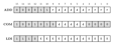
Figure 3: Three AVR instruction encodings, each 16 bits. Fixed opcode bits are shaded; letters are operand bits. In ADD and LDI the operand bits are not contiguous — the register number’s top bit sits apart from the rest, and LDI’s constant is split into two nibbles either side of the register field.
ADD — 0000 11rd dddd rrrr
The opcode is bits 15–10, 0000 11 — six fixed bits, all that is left once the two five-bit register numbers have taken ten of the sixteen. The destination register number is d dddd — five bits, so all 32 registers — and the source is r rrrr. Both have their top bit separated from the other four, and note the order in the middle nibble: the source’s top bit (r, bit 9) comes before the destination’s (d, bit 8), even though the mnemonic writes the destination first.
Worked example: add r23, r7.
| Register | In binary (5 bits) | Split as | |
|---|---|---|---|
rd |
r23 = 16 + 4 + 2 + 1 | 10111 |
d = 1, dddd = 0111 |
rr |
r7 = 4 + 2 + 1 | 00111 |
r = 0, rrrr = 0111 |
Dropping those into 0000 11rd dddd rrrr:
\[\texttt{0000 1101 0111 0111}\]
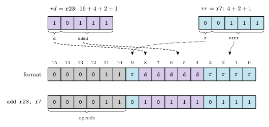
Figure 4: Assembling add r23, r7. Each register number is written as five bits, then torn in two: the top bit goes into the middle nibble and the low four into their own field. Shading, not position, is what tells the two operands apart here. The two guide lines cross because the destination’s bit sits between the source’s two pieces.
COM — 1001 010d dddd 0000
Flip all bits — one’s complement. One register operand, again as d dddd.
Worked example: com r19. r19 = 16 + 2 + 1 = 10011, so d = 1 and dddd = 0011:
\[\texttt{1001 0101 0011 0000}\]
LDI — 1110 KKKK dddd KKKK
Two operand fields:
K— the 8-bit constant, split into two nibbles: the high four bits in the firstKKKKfield, the low four in the last.d— the register number minus 16.
That subtraction is why LDI only reaches r16–r31: the field is four bits, so it can express \(2^4 = 16\) distinct registers, and the ISA spends them on the top half of the register file.
Applying the rule to ldi r16, 73: \(d = 16 - 16 = 0\), so dddd = 0000; \(73 = \texttt{0100 1001}\), so the high nibble is 0100 and the low nibble 1001:
\[\texttt{1110 0100 0000 1001}\]
Flags, by instruction
The reference’s Flags Affected column is worth reading rather than assuming — the flags are defined per instruction, not derived from a single adder. For the instructions above:
| Instruction | Z | C | N | V |
|---|---|---|---|---|
MOV, LDI, SER |
— | — | — | — |
AND, ANDI, OR, ORI, EOR, TST |
from result | unchanged | from result | cleared to 0 |
ADD, ADC, SUB, CP, CPI |
from result | from carry/borrow | from result | signed overflow |
CLR |
always 1 | unchanged | always 0 | cleared to 0 |
COM |
from result | always set to 1 | from result | cleared to 0 |
NEG |
from result | set unless the result is $00 |
from result | set only if the result is $80 |
Two of these will catch you out. The logical operations leave C alone entirely — whatever it held before an and it still holds after. And COM sets C unconditionally, which is not a carry out of anything; it is a defined convention, chosen so that com followed by an increment behaves like a negation.
The CLR row is just the logical row with a result that is guaranteed to be 0x00 — clr rd is eor rd, rd — which makes it the one instruction whose flags you can predict without knowing the operand.
For the shift, rotate and branch instructions, look the flags up in the reference rather than guessing. The one part that is visible in the diagrams above is C: every shift and rotate sets it from the bit that fell out. The rest is defined per instruction, as the paragraph opening this section warns.
For ADD specifically, the manual gives the flags as Boolean formulas over the operand and result bits, writing \(R\) for the result (which equals Rd after the operation):
\[N = R_7 \qquad Z = \overline{R_7}\cdot\overline{R_6}\cdot\overline{R_5}\cdot\overline{R_4}\cdot\overline{R_3}\cdot\overline{R_2}\cdot\overline{R_1}\cdot\overline{R_0}\] \[V = Rd_7 \cdot Rr_7 \cdot \overline{R_7} + \overline{Rd_7}\cdot\overline{Rr_7}\cdot R_7 \qquad C = Rd_7 \cdot Rr_7 + Rr_7 \cdot \overline{R_7} + \overline{R_7}\cdot Rd_7\]
\(Z\) is a NOR over every result bit. \(V\) says overflow happened exactly when both operands had the same sign and the result’s differs — two negatives giving a positive, or two positives giving a negative. And \(S = N \oplus V\), for signed tests. See avr-architecture.
See also
- instruction-set-architecture · avr-architecture · bit-masking
- avr-io-ports — the I/O registers
in/outreach - addressing-modes — the four ways an operand names its value
- avr-program-structure — labels,
jmpand the program skeleton - avr-interrupts —
sei,cli,reti, and which flags an interrupt handler must save - binary-number-representations — one’s and two’s complement, and the \(-128\) to \(255\) range
- 2026-08-27-avr-introduction — Lecture 10
- 2026-09-03-instruction-set-architecture-part-2 — Lecture 12