Lecture 12 — Instruction Set Architecture Part 2
The second half of “what makes an ISA”: the rest of the instructions, the addressing modes, and data types. See avr-instructions for the instruction set as a reference, addressing-modes for the four modes and instruction-set-architecture for the frame.
The four parts of an ISA
The four-part list from 2026-08-31-instruction-set-architecture-part-1, with the lecture each part belongs to:
| 1. Memory models — A. addressable cell size, B. alignment, C. address spaces, D. endianness | Lecture 11 | |
| 2. Registers | Lecture 11 | |
| 3. Instructions | Lecture 12 | |
| 4. Data types | Lecture 12 |
3. Instructions
Instructions are the main feature of an ISA. There are five types. Unlike the list in Lecture 11, arithmetic and logical are one type, split instead by how many operands an instruction takes.
| Type | |
|---|---|
| Input/Output | communicate with I/O devices/ports — in and out, met in Lecture 11 |
| Load/Store | move data from/to memory |
| Move | copy data between registers |
| Arithmetic & Logical | addition, subtraction, bitwise operations — dyadic (two operands, one result) or monadic (one operand, one result) |
| Branching | for deciding which instruction to perform next |
Instructions use various addressing modes, listed at the end of this section.
AVR instruction examples
The instructions from previous lectures. The destination comes first: rd is the destination, rr is the source.
| Instruction | Example or note |
|---|---|
MOV rd, rr — copy rr into rd |
mov r0, r31 → r0 ← r31 |
ADD rd, rr |
add r5, r6 → r5 ← r5 + r6 |
AND rd, rr; OR rd, rr; EOR rd, rr |
and r5, r6 — r5 sits over r6, each column of two bits gives one result bit, and the result overwrites r5 |
COM rd — flip all bits (ones’ complement) |
NEG is the two’s complement counterpart |
LDI rd, K (K is a constant, −128 to 255), r16 to r31 |
the I is for immediate, the first of the addressing modes below |
A logical instruction is eight independent one-bit operations in parallel, which is the whole basis of bit-masking.
IN and OUT
Both are from Lecture 11.
in rd, P |
rd ← I/O register P |
in r5, 0x26 — I/O register 0x26 is TCNT0, i.e. timer/counter 0 |
out P, rr |
I/O register P ← rr |
out PORTD, r6 |
Each takes 1 cell, 1 cycle — one instruction word, one clock cycle. The data memory holds r0 … r31 from address 0, then 64 I/O registers, then 160 extended I/O registers, then SRAM. in reads (R) from the I/O block into the CPU and out writes (W) from the CPU to the I/O block. Details in avr-io-ports.
Load/store instructions
| Load | Load register from memory location | AVR examples: ld, lds |
| Store | Store register value in memory location | AVR examples: st, sts |
They split by addressing mode.
Indirect — the address is in a pointer register, X, Y or Z. X = r27:r26, Y = r29:r28 and Z = r31:r30. The X form:
    ld   r5, X           ; r5 <- Mem[X]
    st   X, r5           ; Mem[X] <- r5
1 cell, 2 cycles.
Direct — the address is in the instruction:
    lds  r5, 0x20        ; r5 <- Mem[0x20]
    sts  0x20, r5        ; Mem[0x20] <- r5
32 bits → 2 cells, 2 cycles. Spelling out a 16-bit address does not fit in one 16-bit instruction word, so these take two.
The SRAM is 2 kB, hence \(2^{11}\) cells, hence 11 bits of address (memory-models). Load (R) and store (W) reach all of the data space, register file and I/O registers included, as in Figure 1 below.
Data movement instructions
Data is usually copied, not moved. There are five types of movement, each with the instruction that does it:
| Movement | Called | AVR |
|---|---|---|
| register → register | move | mov |
| memory → register | load | lds, ld |
| register → memory | store | sts, st |
| I/O register → register | input | in |
| register → I/O register | output | out |
Five movements, three storage locations. Which instruction you need is decided entirely by where the two ends are. The mistake to avoid is confusing an I/O register with a memory address.
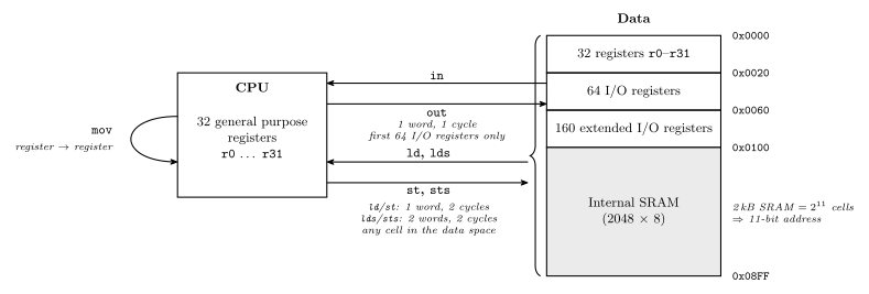
Figure 1: Where data can move. The CPU’s 32 registers are on the left; the data address space is the stack on the right, lowest address at the top. in and out reach only the first 64 I/O registers, one instruction word and one cycle each; ld, st, lds and sts reach any cell of the whole space, which is what the brace marks. The hex boundaries and the SRAM size are from the datasheet memory map in Lecture 11. The 2 kB / \(2^{11}\) cells / 11 bits label sizes the SRAM alone — the stack as a whole runs to 0x08FF.
Figure 1 puts in/out, load/store and data movement in one picture. The register file, the I/O registers and the SRAM are all cells of the same data address space, and the five instructions differ only in which part of it they can reach and how they name it. in/out are the cheap route but stop at I/O register 63. Everything past there has to be reached the long way, by data address, with lds/sts (avr-io-ports).
Dyadic instructions
A dyadic instruction combines 2 operands to produce a result. There are usually two types: arithmetic (ADD r5, r6) and logical, i.e. bitwise (AND r5, r6).
Monadic instructions
A monadic instruction takes one operand and gives one result:
| Operation | Example |
|---|---|
| Setting a register (all 1’s) | SER r16 ≡ ldi r16, 0xFF |
| Clearing a register | CLR r5 |
| Negation (2’s complement) | NEG r5 |
| Inversion (1’s complement negation) | COM r5 |
| Shifting & rotation | the shift and rotate instructions below |
The register numbers differ for a reason: SER r16 but CLR r5. ser expands to ldi, so it inherits the r16–r31 restriction, while clr expands to eor rd, rd and reaches any register (avr-instructions).
Shift instructions
There are three:
- LSL = Logical Shift Left
- LSR = Logical Shift Right
- ASR = Arithmetic Shift Right
They differ in what enters the vacated end and where the departing bit goes. LSL puts 0 into the bottom and sends bit 7 out to C. LSR puts 0 into the top and sends bit 0 out to C. ASR replicates the sign bit into itself and sends bit 0 out to C.
Worked in four bits, as in Figure 2:
| Shift | Worked | Reading |
|---|---|---|
| LSL | 0010 2 → 0100 4 → 1000 8, × 2 each step |
doubling, one place at a time |
| LSR | 1000 (−8) → 0100 4; and 0110 6 ÷2 → 0011 3, unsigned |
halving, unsigned |
| ASR | 1000 (−8) ÷2 → 1100 (−4), the sign bit replicates |
halving, signed |
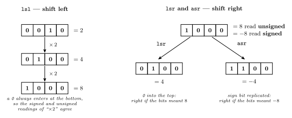
Figure 2: The three shifts worked in four bits for legibility. Left: lsl doubles, 2 → 4 → 8, and a 0 always enters at the bottom so the signed and unsigned readings agree. Right: the same four bits shifted right two ways. 1000 does not say whether it means 8 or \(-8\); the instruction is where that is declared, and each answer is right for one reading and wrong for the other.
The 1000 row is the one that matters. The same four bits are 8 to an unsigned reading and −8 to a signed one. Four bits are used here for legibility; in a real 8-bit register the equivalent pair is 10000000, 128 unsigned and −128 signed. The two shifts give different answers: LSR yields 0100 (4, right for the unsigned reading), ASR yields 1100 (−4, right for the signed one). The instruction is where you declare which interpretation you meant — see binary-number-representations and the reference treatment in avr-instructions.
Rotate instructions
There are two:
- ROL = Rotate Left through Carry
- ROR = Rotate Right through Carry
Each rotate has two halves: the carry goes into the register at the vacated end, and the bit falling out of the other end goes into the carry. A rotate is a shift whose vacated end is fed from C rather than a constant — so the register and the carry flag together behave as a nine-bit ring.
Worked: shifting a 16-bit value
What AVR instruction should follow
lsl r14to perform a multiplication by 2 of the 16-bit unsigned value stored inr13:r14?A.
asl r13, B.lsl r13, C.rol r13or D.rol r14.
C. rol r13. Figure 3 shows why.
    lsl  r14             ; low byte x2; its bit 7 falls out into C
    rol  r13             ; high byte x2, pulling C into its bit 0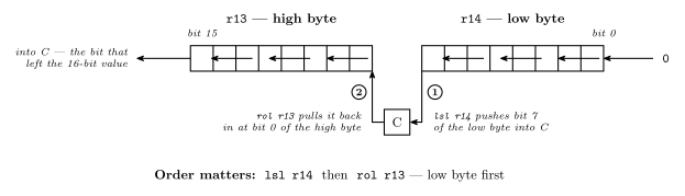
Figure 3: Doubling a 16-bit value in two steps. r13:r14 is one 16-bit value spread over two 8-bit registers, high byte named first. Step 1, lsl r14, shifts the low byte left, feeds a 0 in at bit 0 and pushes its bit 7 out into C. Step 2, rol r13, shifts the high byte left and pulls exactly that bit back in at its bit 0 — which is why rol r13 is the instruction that follows.
The others fail, each differently:
- A.
asl r13and B.lsl r13— the same operation under two names (shifting left, a0always enters), and both feedr13a zero, throwing away the bitr14just produced. - D.
rol r14— the right instruction on the wrong byte.
The general shape: a value wider than the machine is processed low end first, and the carry flag carries between the pieces.
Comparison instructions
A comparison is the same as subtraction, with the result not saved. It sets status register flags (Z, N, C, V …). Equality is what a compare is usually asked, and the flag for that is Z, which is 1 when the two are equal:
cp r5, r6 ; computes r5 - r6, keeps only the flagsThe instruction reference specifies which status register bits are set by which instructions — per instruction, not by one general rule. The table for the instructions met so far is in avr-instructions.
Branch instructions
Branches are based on status register values:
breq label |
Branch if Z = 1 |
brne label |
Branch if Z = 0 |
Compare then branch is the entire conditional. Labels and the program skeleton the branches sit in are in avr-program-structure.
Addressing modes
Instruction operands can come from different places:
| Mode | AVR example | |
|---|---|---|
| Immediate | An operand value is in the instruction | andi r17, 0xBA |
| Register | Only register numbers in instruction | and r18, r19 |
| Direct | Memory address is in the instruction | lds r15, $1234 |
| Indirect | Memory address in register; the register number is in the instruction | ld r5, X |
The direct form occupies two instruction words (32 bits). That is the cost that distinguishes it from indirect, which stays one word.
These addressing mode names are as per Tanenbaum, Structured Computer Organization. The AVR instruction set manual uses different names, so match on the behaviour, not the word. Full treatment in addressing-modes.
4. Data types
Numeric
- Integers of different lengths (8, 16, 32, 64 bits), possibly signed or unsigned
- Floating point numbers, e.g. 32 bits (single precision) or 64 bits (double precision) — \(A = \pi r^2\) with \(3.14\) is the case that forces the type
- Many others
Non-numeric
- Boolean (0 means false, 1 means true) — stored in a whole byte or word
- Bit-map (collection of Booleans, e.g. 8 in a byte)
- Characters
- Pointers (memory addresses)
A Boolean is a bit’s worth of information but costs a whole byte, unless you pack eight of them into one. That is what a bit-map is, and why bit-masking exists as a technique.
Hardware support
Different machines provide hardware support for different data types.
Intel-64 Architecture
| Data type | 8 bits | 16 bits | 32 bits | 64 bits | 128 bits |
|---|---|---|---|---|---|
| Signed integer | ✓ | ✓ | ✓ | ✓ | |
| Unsigned integer | ✓ | ✓ | ✓ | ✓ | |
| BCD integer | ✓ | ||||
| Floating point | ✓ | ✓ |
Atmel AVR
| Data type | 8 bits | 16 bits | 32 bits | 64 bits | 128 bits |
|---|---|---|---|---|---|
| Signed integer | ✓ | ||||
| Unsigned integer | ✓ | ||||
| BCD integer | |||||
| Floating point |
Two ticks against eleven. The AVR supports exactly one data type in hardware: an 8-bit integer, signed or unsigned.
Other data types can be supported through software. For example, 16-bit integer operations can be built out of 8-bit operations, using a sequence of instructions. So the table is a statement about cost, not possibility — nothing in it is unavailable, it just takes more instructions and more cycles.
AVR example of 16-bit addition
Add the 16-bit quantity
r5:r4tor11:r10. (Result should be inr11:r10.)
Two instructions, worked as long addition in Figure 4:
    add  r10, r4         ; r10 <- r10 + r4        (low bytes; carry out lands in C)
    adc  r11, r5         ; r11 <- r11 + r5 + C    (high bytes, plus that carry)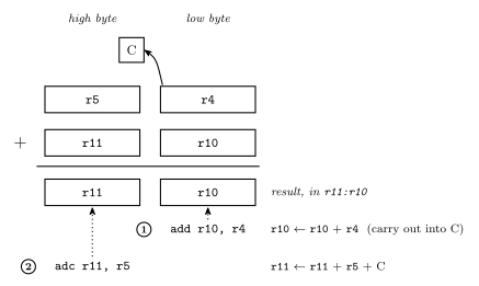
Figure 4: 16-bit addition as long addition with one byte per column, high byte on the left. Step 1, add r10, r4, adds the low column and leaves any carry out of bit 7 in C. Step 2, adc r11, r5, adds the high column and that carry. This is the whole of how an 8-bit machine does 16-bit arithmetic.
ADD on the low bytes leaves any carry out of bit 7 in C; ADC on the high bytes adds it back in. It is column-by-column carrying, exactly as on paper, one byte per column — and nothing may sit between the two instructions that disturbs C.
Summary
| Memory models | Lecture 11 |
| Registers | Lecture 11 |
| Instructions | ✓ |
| Data types | ✓ |
Knowing all these details is enough to write machine code that runs on the CPU and to build the CPU.
See also
- avr-instructions — every instruction here, with encodings and flags
- addressing-modes — the four modes in full
- instruction-set-architecture — the four pillars, and the data type tables
- avr-io-ports · avr-program-structure · bit-masking · binary-number-representations
- 2026-08-31-instruction-set-architecture-part-1 — Lecture 11
- week6-lab-avr-io-ports — Lab 10, which assumes this lecture