Bit Masking
Using a bitwise operation against a constant mask to touch only the bits you care about, leaving the rest alone. See boolean-algebra for the underlying laws and avr-instructions for the instructions used here. The same masks, written from the bit names in the AVR’s header files, are how every I/O register is set up in C: see set, clear and toggle and writing register bits by name.
Sometimes you are interested in only a few bits of a register. A bitwise AND can mask out the bits that are not of interest — and more generally, masking can selectively set, clear, toggle or extract bits.
The reason any of this is possible is that a bitwise instruction is not one eight-bit operation. It is eight independent one-bit operations running in parallel, and the two operands’ bit \(i\) decide result bit \(i\) with no reference to any other column.
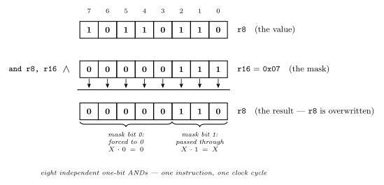
Figure 1: Why a mask works, one column at a time. Two rows of bits, an arrow down out of each column into a result row that overwrites the destination: here and r8, r16 with the mask 0x07, extracting the low three bits. The eight columns never interact — one mask bit decides one result bit, a 1 passing the value’s bit through and a 0 forcing it to zero — and all eight happen at once in a single instruction. Choosing a mask is therefore nothing more than deciding, position by position, which bits to keep.
Read Figure 1 column by column and the technique stops needing to be memorised: since the columns are independent, choosing a mask is just choosing, for each of the eight positions separately, whether that position gets passed through or forced.
The three identities that make it work
Each of AND, OR and XOR has a value that passes a bit through unchanged and a value that forces it. That pairing is the whole technique.
| \(X \cdot 0\) | \(X \cdot 1\) | \(X \cdot X\) | |
|---|---|---|---|
| AND | \(= 0\) | \(= X\) | \(= X\) |
| \(X + 0\) | \(X + 1\) | \(X + X\) | |
|---|---|---|---|
| OR | \(= X\) | \(= 1\) | \(= X\) |
| \(X \oplus 0\) | \(X \oplus 1\) | \(X \oplus X\) | |
|---|---|---|---|
| XOR | \(= X\) | \(= \overline{X}\) | \(= 0\) |
Reading off the pass-through and force columns gives the operation to reach for:
| To do this to the selected bits | Use | Mask bit = 1 on | Mask bit = 0 on |
|---|---|---|---|
| Clear them to 0 | AND |
the bits to keep — \(X \cdot 1 = X\) | the bits to clear — \(X \cdot 0 = 0\) |
| Set them to 1 | OR |
the bits to set — \(X + 1 = 1\) | everything else — \(X + 0 = X\) |
| Toggle them | EOR |
the bits to flip — \(X \oplus 1 = \overline{X}\) | everything else — \(X \oplus 0 = X\) |
| Extract them (others zeroed) | AND |
the bits to keep — \(X \cdot 1 = X\) | the bits to discard — \(X \cdot 0 = 0\) |
Note the asymmetry: AND’s mask is 1 on the bits you keep, whereas OR’s and XOR’s masks are 1 on the bits you act on. Getting that backwards is the usual bug — with AND you write the mask for what survives, with the other two for what changes.
\(X \oplus X = 0\) is the other one worth remembering: XORing a register with itself is the cheapest way to zero it.
In AVR assembly
The masks are ordinary constants, so the bitwise instructions of avr-instructions do the work. On AVR the immediate forms (andi, ori) only reach r16–r31; for a low register, load the mask into a high register and use the two-register form.
Extract the least significant three bits of r7 into r8, other bits of r8 zero.
    mov  r8, r7          ; copy the source
    ldi  r16, 0x07       ; mask 0000 0111 — keep the bottom three
    and  r8, r16         ; everything else forced to 0
Toggle the most significant four bits of r9, other bits unchanged.
    ldi  r16, 0xF0       ; 1111 0000 — flip the top four
    eor  r9, r16         ; bottom four XOR 0, so unchanged
Clear the least significant four bits of r10, other bits unchanged.
    ldi  r16, 0xF0       ; 1 on the bits to KEEP
    and  r10, r16        ; bottom four AND 0 -> 0
Set the most significant four bits of r11 to 1, other bits unchanged.
    ldi  r16, 0xF0       ; 1 on the bits to set
    or   r11, r16        ; bottom four OR 0, so unchanged
Note how 0xF0 appears as the mask in three of these with three different meanings — keep, flip, set — decided entirely by the instruction it is paired with.
In C
The same four operations with C’s bitwise operators (c-operators), which is how every AVR C program touches its ports. The masks are the same; the immediate-register restriction disappears, since the compiler chooses the registers.
| Operation | Operator | Example | Reads as |
|---|---|---|---|
| Clear particular bits | & with 0s on the bits to clear |
var = PINB & 0x0F; |
keep the low nibble, zero the high |
| Test particular bits | & with a 1 on the bit to test |
if (PINB & 0x02) … |
true if bit 1 is set |
| Set particular bits | \| with 1s on the bits to set |
PORTC = PINB \| 0x80; |
force bit 7 to 1 |
| Invert particular bits | ^ with 1s on the bits to flip |
PORTC = PINB ^ 0x0F; |
flip the low nibble |
Write the mask as a shift, not a hex constant: (1<<5) says bit 5 where 0x20 has to be decoded, and the header files name every register bit as a bit number for exactly this use (c-preprocessor-and-avr-headers):
DDRB  = (1<<5);                 /* bit 5 output, every other bit input: REPLACES the register */
DDRB |= (1<<4) | (1<<3);        /* bits 3 and 4 output, the rest unchanged: read-modify-write */
DDRB &= ~(1<<3);                /* bit 3 back to input, the rest unchanged                    */
PORTC ^= (1<<0);                /* toggle bit 0                                              */
TCCR1B = (1<<WGM12) | (1<<CS11) | (1<<CS10);   /* named bits, ORed into one value            */
The difference between the first two lines is the one that bites: = writes the whole register and silently sets the other seven bits to 0, |= ORs into what is already there. In assembly the second line is three instructions — in, ori, out — and the C compiler emits exactly those (week8-lab-avr-c-programming). For a single-bit clear the mask is the complement of the set mask, ~(1<<n), which is why clear bit 3 is &= ~(1<<3) and not &= (1<<3).
The test idiom needs no comparison. PINB & 0x02 is 0x02 when bit 1 is set and 0 when it is not, and C treats any non-zero value as true (c-control-flow) — so if (PINB & 0x02) is right and if ((PINB & 0x02) == 1) is always false, because the masked value is 2, never 1.
Set, clear and toggle on an I/O register
Changing one bit of an I/O register, and only that bit, is one of three lines. Each reads the register, combines it with a one-bit mask and writes it back:
| To | Write | The mask | Why the other bits survive |
|---|---|---|---|
| set bit n | REG \|= (1<<n); |
a 1 on bit n | \(X + 0 = X\) |
| clear bit n | REG &= ~(1<<n); |
a 0 on bit n, 1s elsewhere | \(X \cdot 1 = X\) |
| toggle bit n | REG ^= (1<<n); |
a 1 on bit n | \(X \oplus 0 = X\) |
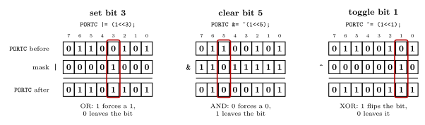
Figure 2: Set, clear and toggle on one register byte. Each panel starts from the same value of PORTC, 0110 0101, and changes one bit, outlined, with a single read-modify-write. The mask is a 1 shifted to the bit’s position, complemented for a clear. In every other column the mask holds the value that leaves a bit alone: 0 for OR and XOR, 1 for AND. Set gives 0110 1101, clear gives 0100 0101 and toggle gives 0110 0111, and each time the other seven bits are untouched.
Toggle is not enable. TIMSK2 ^= (1<<OCIE2A); turns the timer 2 compare A interrupt on only if it was off, and a second run turns it off again. To enable whatever the bit was before, set it with |=; to disable, clear it with &= ~. Toggling is for things meant to alternate, like an LED blinking.
The register has to be one that stores what is written. PORTx and DDRx do. PINx does not: it reads the pins, and on the ATmega324A a 1 written to one of its bits toggles the matching PORTx bit, so a read-modify-write on PINx changes the wrong bits (avr-io-ports).
Writing register bits by name
When setting or clearing bits of an I/O register, be explicit about which bits. Three ways to write the same value, from worst to best:
TCCR1B = 10;                          /* poor:   a number                    */
TCCR1B = 0x0A;                        /* better: the pattern, 0000 1010      */
TCCR1B = (1<<WGM12) | (1<<CS11);      /* best:   the bits, by name           */
WGM12 is bit 3 of TCCR1B and CS11 is bit 1, so all three are 0000 1010. Only the last says which bits, so a reader can check them against the datasheet without decoding anything: CTC mode, clock divided by 8 (avr-timers-and-counters). It costs nothing, either. The compiler works out (1<<WGM12) | (1<<CS11) while compiling, and all three lines become the same instructions.
The names are bit numbers. The device header that <avr/io.h> includes defines every bit name as the bit’s position in its register:
#define WGM02 3A name is not a mask; 1<< makes it one (c-preprocessor-and-avr-headers). The names are the datasheet’s, and the datasheet has errors in places, so the I/O register summary at the back is the one to check a name against.
Assembly uses the same names. In ldi r16, (1<<WGM02)|(1<<CS01) the assembler works out the constant, 0x0A, and the instruction stored is ldi r16, 0x0A.
A name belongs to one register. WGM12 and WGM02 are both 3, so (1<<WGM12) written into TCCR0B sets WGM02, and the compiler cannot notice, because all it sees is the number 3. Pair each name with the register whose datasheet entry defines it. The same byte 0x0A is CTC mode in TCCR1B and a reserved mode in TCCR0B (2026-10-05-more-io).
Masking sets the status flags too
Status register flags will be set also — a mask operation is a real ALU operation, not a free one. AND, OR and EOR all clear V and set N and Z from the result (C is untouched); see avr-architecture.
That side effect is often the actual point. andi r16, 0x01 keeps only bit 0, so:
\[Z = 1 \iff \text{bit 0 of } \texttt{r16} \text{ is } 0 \iff \texttt{r16} \text{ is even}\]
which makes a single masked AND an even/odd test. Any single-bit mask turns the Z flag into a test of that one bit — and tst rd, which is just and rd, rd, is the degenerate case that tests the whole register against zero.
Common mistakes
&= (1<<n)to clear bit n. That keeps bit n and clears the other seven. A clear’s mask is the complement,~(1<<n).=where|=was meant.DDRB = (1<<5)makes PB5 an output and every other pin of port B an input.- A bit name without the shift.
TCCR1B |= WGM12;ORs in the number 3,0000 0011, which setsCS11andCS10, clock divided by 64, and leavesWGM12alone. - A bit name in the wrong register.
(1<<WGM12)inTCCR0BsetsWGM02. ^=to enable. A toggle enables only from off; run twice, it disables.- A read-modify-write on
PINx. WritingPINxtoggles outputs, so it cannot clear or set a bit. - Getting AND’s mask backwards. With AND the 1s mark the bits to keep; with OR and XOR they mark the bits to change.
if ((x & mask) == 1). The masked value is the mask’s own value, so the test is false unless the mask is bit 0. Test for non-zero.
See also
- boolean-algebra · avr-instructions · avr-architecture
- avr-io-ports — one bit of a port in C and assembly, and why
PINxis different - avr-timers-and-counters — the
TCCRnBfields named in the examples - 2026-10-05-more-io — Lecture 19: poor, better and best,
TIMSK2toggled - week5-lab-avr-assembly-one — Lab 9, where these snippets are the exercise
- week8-lab-avr-c-programming — Lab 11, the same operations in C · c-operators · c-preprocessor-and-avr-headers