Instruction Set Architecture
The layer where software meets hardware: what a machine instruction is, what an ISA specifies, and why assembly language exists. See cpu-organisation for the hardware below this line and avr-instructions for a real instruction set.
Machine instructions
A machine instruction is a pattern of bits. 0000 1101 0111 0111 is a valid Atmel AVR instruction. Instructions typically consist of two things:
- Opcode (operation code) — defines the operation, e.g. addition.
- Operands — what is being operated on, e.g. particular registers or a memory address.
So one word of machine code says what to do and what to do it to, packed into fixed bit fields. Which bits mean which is entirely a matter of convention — and that convention is the ISA.
The ISA
An Instruction Set Architecture is a specification — i.e. a document. It specifies the interface between hardware and software.
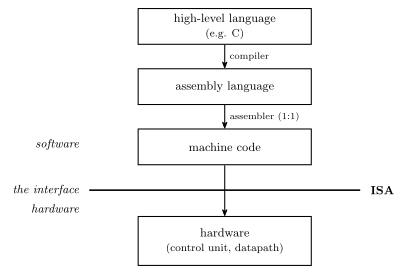
Figure 1: The ISA as an interface. Software above the line is written and compiled without knowing how the hardware works; hardware below the line is designed without knowing what program will run. The only thing both sides must agree on is which bit patterns mean what — and that agreement is a document, not a circuit.
The point of drawing it as a line is that the ISA is the only thing the two sides have to agree on. A compiler writer needs the ISA and nothing else about the chip; a chip designer needs the ISA and nothing else about the programs that will run.
Microarchitecture
Microarchitecture = the architecture of the control unit — i.e. the state machine (gates and flip-flops etc.) that implements the control unit.
This is the same state-machines material from earlier in the course, applied at the scale of a whole processor: the control unit is a state machine whose job is to emit the right control signals, in the right order, for whatever the instruction register holds.
ISA vs microarchitecture
One ISA can be implemented by many different microarchitectures. The specification says what the bit patterns mean; it does not say how a chip must go about honouring them.
| ISA | Implemented by |
|---|---|
| 8086 | many processors, in different ways |
| Pentium | Pentium … Pentium IV … Core2Duo … i7 (each in different ways), various AMD devices, and other manufacturers |
This is why a program compiled decades ago still runs: the ISA held still while the microarchitecture beneath it was rebuilt many times over.
What makes an ISA?
Four things:
- Memory models
- Registers
- Instructions
- Data types
If you know all these details, you can write machine code that runs on the CPU and build the CPU.
This is the completeness test for a specification: both sides of the line in Figure 1 have to be constructible from the document alone, and nothing else about the chip may be needed by either.
1. Memory models
How does memory look to the CPU? Four issues decide it — addressable cell size, alignment, address spaces and endianness — treated in full in memory-models.
2. Registers
Two types of register:
- General purpose — used for temporary results etc. On AVR, r0–r31.
- Special purpose, e.g.
- Program Counter (PC)
- Stack pointer (SP)
- Input/Output registers — 224 of them on the ATmega324A, see avr-io-ports
- Status register — N, Z, C, V among others. Tanenbaum calls this the Program Status Word.
Some other registers are part of the microarchitecture, NOT the ISA — e.g. the Instruction Register (IR). The programmer doesn’t need to know about these, and can’t directly change or use them.
That distinction is the cleanest illustration of what an ISA actually is. The IR unquestionably exists and holds the instruction being executed (fetch-decode-execute-cycle) — but no instruction names it, so it is invisible to software and a chip designer is free to change or remove it. The PC is the opposite case: jmp writes it, so it has to be in the specification. Existing in the hardware is not the criterion; being reachable from an instruction is.
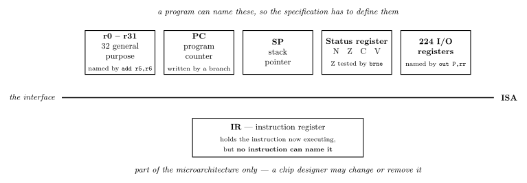
Figure 2: The same interface line as in the previous figure, with the machine’s registers sorted across it. The five above the line are part of the ISA; four of them carry an example of an instruction that names the register, and the SP box carries none. The single box below, the IR, is part of the microarchitecture only. Nothing about a register’s size or importance decides which side it lands on — only whether some instruction can refer to it.
The AVR’s own answer to this pillar — the regularity of r0–r31, the r16–r31 exception, and the X/Y/Z pointer pairs — is in avr-architecture.
3. Instructions
This is the main feature of an ISA. Instruction types include:
| Type | Does |
|---|---|
| Input/Output | communicate with I/O devices/ports |
| Load/Store | move data from/to memory |
| Move | copy data between registers |
| Arithmetic | addition, subtraction, … |
| Logical | Boolean operations |
| Branching | for deciding which instruction to perform next |
The Input/Output row is the one where the AVR’s answer is least obvious. The ATmega324A’s 224 I/O registers are all reachable by ld/st at their data-memory addresses 32 to 255 ($20 to $FF), but only the first 64 also get the short in rd, P / out P, rr form that names an I/O register by its own number P — because P is a six-bit field and \(2^6 = 64\). The other 160, the “extended” I/O registers, can only be reached the long way. The mechanics, the numbering offset and the register list are in avr-io-ports.
With arithmetic and logical merged, the same set can be cut the other way instead — by how many operands an instruction takes:
- Dyadic — two operands, one result
- Monadic — one operand, one result
And instructions use various addressing modes: how an operand says where its value is, covered in addressing-modes.
The AVR instructions met so far, sorted into these boxes, are in avr-instructions.
4. Data types
Numeric
- Integers of different lengths (8, 16, 32, 64 bits), possibly signed or unsigned
- Floating point numbers, e.g. 32 bits (single precision) or 64 bits (double precision)
- Many others not listed
Non-numeric
- Boolean (0 means false, 1 means true) — stored in a whole byte or word
- Bit-map (collection of Booleans, e.g. 8 in a byte)
- Characters
- Pointers (memory addresses)
Different machines provide hardware support for different data types. Two ends of the range:
Intel-64 Architecture
| Data type | 8 bits | 16 bits | 32 bits | 64 bits | 128 bits |
|---|---|---|---|---|---|
| Signed integer | \(\checkmark\) | \(\checkmark\) | \(\checkmark\) | \(\checkmark\) | |
| Unsigned integer | \(\checkmark\) | \(\checkmark\) | \(\checkmark\) | \(\checkmark\) | |
| BCD integer | \(\checkmark\) | ||||
| Floating point | \(\checkmark\) | \(\checkmark\) |
Atmel AVR
| Data type | 8 bits | 16 bits | 32 bits | 64 bits | 128 bits |
|---|---|---|---|---|---|
| Signed integer | \(\checkmark\) | ||||
| Unsigned integer | \(\checkmark\) | ||||
| BCD integer | |||||
| Floating point |
The only data type an AVR supports in hardware is an 8-bit integer, signed or unsigned. There is no 16-bit integer type, no floating point, no BCD.
Other data types can be supported through software! e.g. 16-bit integer operations can be built out of 8-bit operations, using a sequence of instructions — which is exactly what the two-instruction 16-bit addition in avr-instructions does. So the hardware/software line here is about cost, not possibility: anything missing from the table can still be computed, it just takes more instructions and more cycles. Floating point is the costly case: one float multiply is hundreds of instructions (floating-point-numbers), which is why fractions on the AVR are usually kept as fixed-point-numbers.
Assembly language
Machine code is too hard to program in. Assembly language is used instead:
- Human readable (just!).
- Converted into machine code by software called an assembler.
Two Atmel AVR examples:
| Assembly | Meaning |
|---|---|
add r3,r4 |
r3 ← r3 + r4 |
inc r22 |
r22 ← r22 + 1 |
The important structural detail is in the arrows of Figure 1: a high-level language compiles one-to-many — one line of C becomes however many instructions it takes — whereas assembly assembles one-to-one. Each assembly instruction is one machine instruction, written in a form a person can read. That is the whole of what an assembler buys you, and it is why assembly is still “programming the machine” in a way C is not.
The toolchain
For CSSE2010 the assembler is Microchip Studio, and two supplied tutorials walk through it end to end: Intro to Microchip Studio (create an assembler project, pick the device, edit, build, and step through the simulator) and Microchip Studio C Tutorial (the same for a GCC C project). Both are click-through guides to follow at the machine rather than material to learn — they are on Blackboard, and the labs are where they get used.
See also
- memory-models · addressing-modes — pillars 1 and 3, in full
- cpu-organisation · fetch-decode-execute-cycle · state-machines
- avr-architecture · avr-instructions · avr-io-ports · avr-program-structure
- assembly-process — what the assembler does besides translating: directives, segments and two passes · compilation-and-linking — the compiler’s one-to-many road, through object files and the linker
- 2026-08-27-avr-introduction — Lecture 10
- 2026-08-31-instruction-set-architecture-part-1 — Lecture 11
- 2026-09-03-instruction-set-architecture-part-2 — Lecture 12