Fetch-Decode-Execute Cycle
What the control unit actually does: a continuous cycle over the datapath, issuing control signals in the right order for whatever instruction it just read. See cpu-organisation for the blocks involved and arithmetic-logic-unit for the one being driven.
The cycle
The control unit operates in a continuous cycle on the datapath:
| Stage | What happens |
|---|---|
| Fetch | Fetch an instruction from memory and bring it inside the CPU. Two special purpose registers involved — PC and IR |
| Decode | Resolve the operation (opcode) and operands (variables) |
| Execute | Control signals are issued and the operation takes place in the datapath |
Stated as steps:
- Fetch the next instruction from memory into the Instruction Register (IR).
- Change the Program Counter (PC) to point to the next instruction.
- Determine the type of (decode) the instruction just fetched — i.e. look at the opcode.
- Execute the instruction.
- Return to step 1.
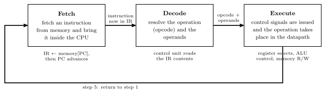
Figure 1: The cycle as a loop: a three-stage pipeline. Each box holds a one-line description of its stage, each arrow carries what the stage leaves behind for the next one, and the notes under the boxes summarise steps 1–4 above.
Step 2 advances the PC before the instruction executes, which is why a jump instruction works by overwriting the PC rather than by suppressing the increment.
The datapath
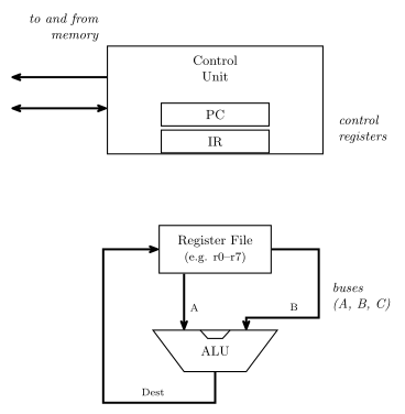
Figure 2: The datapath the cycle runs on. The control unit holds PC and IR and talks to memory; below it, the register file puts two values onto the A and B buses, the ALU combines them, and the result returns on the destination bus to be written back into a register.
The question this raises — and the one the control unit exists to answer — is how do we control this? Specifically:
- How do we tell the ALU what to do?
- How do we choose what register values are placed on the A and B buses?
- How do we choose which register receives the result from the destination bus?
- How do we know when to read or write memory?
Control signals
Each of those questions is answered by a bundle of wires out of the control unit. For a machine with 8 registers and the ALU of arithmetic-logic-unit:
| Signal | Width | Answers |
|---|---|---|
| A register select | 3 | which register drives the A bus (\(2^3 = 8\) registers) |
| B register select | 3 | which register drives the B bus |
| Destination select | 3 | which register the result is written back into |
| ALU control | 6 | what the ALU does — \(F_1\), \(F_0\), ENA, INVA, ENB, INC |
| Memory read/write | 1 | whether this is a read or a write |
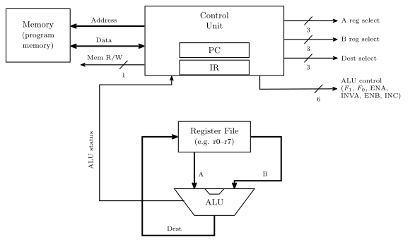
Figure 3: The same datapath with every control signal named. Added to the previous figure: the memory block, the Address, Data and Mem R/W labels, the five bundles with their widths, and the ALU status path back into the control unit. The bundles are drawn as labelled stubs: A/B/Dest select drive the register file, ALU control drives the ALU. Widths are marked with a slash and a number; the course also letters the width beside a plain arrow, and neither is fixed as the standard. Everything except the memory block sits inside the CPU.
Plus the address and data connections to memory itself. The widths are not arbitrary: three bits because there are eight registers, and six bits because the ALU has exactly six control inputs.
Control signals come from the control unit, which must generate them in the right order for a given instruction — and which instruction that is, is determined by the contents of the Instruction Register.
So a line of high-level code like r5 = r0 + r2 becomes: A select = 0, B select = 2, destination select = 5, ALU control = the \(A + B\) row of the combinations table, memory read/write idle.
Data influencing control
The IR is not enough. The control unit can’t operate without knowing something about the data — for example, if a for-loop variable is supposed to count from 10 down to 0, how does the control unit know when it gets there?
The answer is the status register: determined by ALU operations, it stores the status of the last ALU operation and is available to the control unit. This closes the loop — the ALU’s results feed back into the control unit and change what it does next, which is what makes conditional branching possible at all. It is the return path drawn in Figure 3, and it is what a source-level if (x < 0) compiles down to.
ALU status flags
The ALU emits, alongside its result, a summary of what happened during the last operation. Typically stored in a special purpose register called the STATUS register:
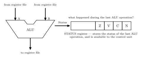
Figure 4: The ALU’s second output. The result goes back to the register file; alongside it the ALU reports what happened, and those flags land in the STATUS register where the control unit can read them. The ALU is drawn as a notched trapezoid here; the block diagram in the ALU note draws the same block as a plain rectangle, and the course uses both shapes. The register is drawn as four named cells at the right-hand end of a wider register. That is shorthand, not a bit-position claim — the AVR’s own SREG orders and numbers its bits differently, see the AVR architecture note.
| Flag | Name | Asks |
|---|---|---|
| Z | zero | was the last result 0? |
| V | overflow | did the last addition/subtraction overflow, assuming it was a two’s complement operation? |
| C | carry | was a carry out generated? |
| N | negative | was the result negative if considered as two’s complement — i.e. what is the sign bit? |
V and N both presuppose a two’s complement interpretation while C does not — the hardware computes all four regardless, and it is the program’s business to read the ones that mean something for the operation it just did. See binary-number-representations, and 2026-08-04-binary-arithmetic for the overflow rules V implements.
Worked example
What values are in the status register flags after the operation \(8_{10} - 9_{10}\) on a 5-bit ALU?
First, \(-9\) in 5-bit two’s complement: \(9 = 01001\), invert to \(10110\), add one to get \(10111\). Then add, tracking the carry into and out of the sign column:
\[\begin{array}{crl} \text{carry into MSB} \rightarrow & 0\phantom{0000} & \\ & 01000 & \\ + & 10111 & \\ \hline \text{carry out} = 0 \rightarrow & 11111 & \end{array}\]
The result is \(11111\), with no carry out of the top bit. So:
| Flag | Value | Why |
|---|---|---|
| Z | 0 | the result \(11111\) is not zero |
| C | 0 | no carry out of the most significant bit |
| V | 0 | the carry into the sign column and the carry out of it agree, both 0 — and indeed \(8 + (-9) = -1\) is comfortably in range for 5-bit two’s complement |
| N | 1 | the sign bit is 1 — the result is negative |
And indeed \(11111\) read as two’s complement is \(-1\), which is \(8 - 9\).
See also
- cpu-organisation · arithmetic-logic-unit
- binary-number-representations — two’s complement, overflow and the sign bit
- 2026-08-04-binary-arithmetic — the \(C_{in} \oplus C_{out}\) overflow test the V flag implements
- avr-architecture — the AVR’s own status register, bit by bit
- state-machines — the control unit is itself a state machine, sequencing signals for each instruction
- 2026-08-24-alu-and-control-unit — Lecture 9