Arithmetic Logic Unit
The ALU is versatile hardware which can perform various operations based on some control inputs — it does considerably more than adding. See cpu-organisation for where it sits in the CPU, and combinational-logic-blocks and logic-gates for the pieces it is built from.
The ALU as a block
A function/control input indicates the operation the ALU is to perform: addition, increment (\(+1\)), subtraction, bitwise AND, bitwise OR, and so on.
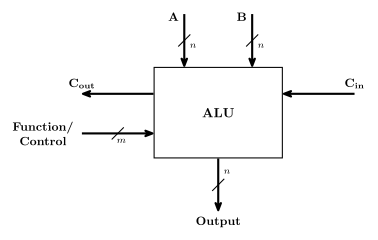
Figure 1: The ALU as a block. A and B are n-bit data inputs and Output is the n-bit result; the m-bit Function/Control input selects which operation is performed, and the carry in and out let several ALUs be chained. Slashes mark bus widths.
Like adders, ALUs can be made up from 1-bit slices — an \(n\)-bit ALU is \(n\) identical circuits, one per bit position.
The 1-bit ALU (bit slice)
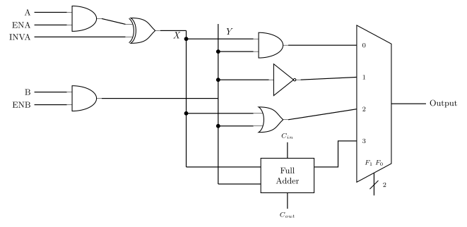
Figure 2: One bit slice. The ENA/INVA/ENB gates on the left condition the two data inputs into internal signals X and Y; the four function blocks in the middle compute AND, NOT, OR and sum from them simultaneously; the multiplexer selects which one reaches the output, under the F1 F0 select. Cin and Cout belong to the full adder, and are what chain one slice to the next.
\(F_1\) and \(F_0\) select which of the four function blocks reaches the output:
| \(F_1 F_0\) | Function | |
|---|---|---|
| 00 | A and B | logical |
| 01 | invert B | logical |
| 10 | A or B | logical |
| 11 | A plus B | arithmetic |
Two levels of control
The bit slice has control inputs at two distinct levels, and keeping them apart is what makes the combinations table below readable:
- Permutations of the data inputs —
ENA,ENBandINVAcondition A and B before any function sees them. - Function select — \(F_1 F_0\) picks which operation’s result is actually output.
The conditioning gates are worth working out explicitly, because most of the useful ALU tricks come from them rather than from the function select. Writing \(X\) for the conditioned A line and \(Y\) for the conditioned B line:
\[X = (A \cdot \text{ENA}) \oplus \text{INVA} \qquad\qquad Y = B \cdot \text{ENB}\]
| ENA | INVA | \(X\) | ENB | \(Y\) | |
|---|---|---|---|---|---|
| 0 | 0 | 0 | 0 | 0 | |
| 0 | 1 | 1 | 1 | \(B\) | |
| 1 | 0 | \(A\) | |||
| 1 | 1 | \(\overline{A}\) |
So the A line can be forced to a constant 0, a constant 1 (all ones across the whole word, i.e. \(-1\) in two’s complement), \(A\) itself, or \(\overline{A}\) — and that constant-generating ability is what lets one ALU compute \(-1\), \(B-1\) and \(B - A\) without any dedicated hardware for them.
INC is the third conditioning input: it is the carry into the least significant slice, 0 for addition and 1 for increment.
Cascading into an \(n\)-bit ALU
A machine word is \(n\) bits (often 8, 16, 32, …), and an \(n\)-bit ALU is built from \(n\) identical bit slices.
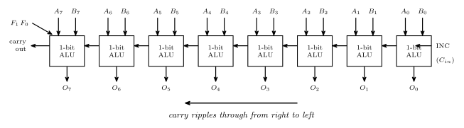
Figure 3: An 8-bit ALU as eight cascaded slices. Each slice takes its own bit of A and B and produces its own bit of the output; the carry out of one slice is the carry in of the next, rippling from right (least significant) to left. F1, F0, ENA, ENB and INVA are shared by every slice, so all eight always perform the same operation.
\(F_1\), \(F_0\), ENA, ENB and INVA are shared between all bit slices — there is one function select for the whole ALU, not one per bit. Only the carry is per-slice, and it ripples through from right to left, which is exactly the ripple-carry adder behaviour from earlier in the course.
Useful combinations of ALU inputs
Everything a single ALU can be made to do, by choosing the six control inputs. This table is worth understanding rather than memorising — each row follows from \(X\), \(Y\) and the function select above.
| \(F_1\) | \(F_0\) | ENA | ENB | INVA | INC | Function |
|---|---|---|---|---|---|---|
| 1 | 0 | 1 | 0 | 0 | 0 | \(A\) |
| 1 | 0 | 0 | 1 | 0 | 0 | \(B\) |
| 1 | 0 | 1 | 0 | 1 | 0 | \(\overline{A}\) |
| 0 | 1 | 1 | 1 | 0 | 0 | \(\overline{B}\) |
| 1 | 1 | 1 | 1 | 0 | 0 | \(A + B\) |
| 1 | 1 | 1 | 1 | 0 | 1 | \(A + B + 1\) |
| 1 | 1 | 1 | 0 | 0 | 1 | \(A + 1\) |
| 1 | 1 | 0 | 1 | 0 | 1 | \(B + 1\) |
| 1 | 1 | 1 | 1 | 1 | 1 | \(B - A\) |
| 1 | 1 | 0 | 1 | 1 | 0 | \(B - 1\) |
| 1 | 1 | 1 | 0 | 1 | 1 | \(-A\) |
| 0 | 0 | 1 | 1 | 0 | 0 | \(A\) AND \(B\) |
| 1 | 0 | 1 | 1 | 0 | 0 | \(A\) OR \(B\) |
| 1 | 0 | 0 | 0 | 0 | 0 | \(0\) |
| 1 | 1 | 0 | 0 | 0 | 1 | \(1\) |
| 1 | 0 | 0 | 0 | 1 | 0 | \(-1\) |
Reading a few rows to see the pattern:
- \(A\) — select OR (\(F_1F_0 = 10\)), pass \(A\) through (\(X = A\)), force the other side to zero (\(Y = 0\) via \(\text{ENB} = 0\)). \(A + 0 = A\) in the OR sense.
- \(-1\) — select OR, force \(X\) to all ones (\(\text{ENA}=0\), \(\text{INVA}=1\)) and \(Y\) to zero. All ones is \(-1\) in two’s complement.
- \(B - 1\) — select the adder, \(Y = B\), $X = $ all ones \(= -1\), and no extra carry. So \(B + (-1)\).
- \(1\) — select the adder with both inputs forced to zero and \(\text{INC} = 1\), so the result is the carry alone.
Worked example — computing \(B - A\)
What are the values of \(F_1\), \(F_0\), ENA, ENB, INVA and INC to calculate \(B - A\)?
The route is two’s complement negation:
\[B - A = B + (-A) = B + (\overline{A} + 1) = B + \overline{A} + 1\]
So the ALU needs \(\overline{A}\) on one adder input, \(B\) on the other, and a carry of 1 into the bottom slice:
| Control | Value | Why |
|---|---|---|
| \(F_1 F_0\) | 1, 1 | select the adder |
| ENA | 1 | let \(A\) through |
| INVA | 1 | invert it, giving \(\overline{A}\) |
| ENB | 1 | let \(B\) through |
| INC | 1 | the \(+1\) of the negation |
Laid out as a column addition across the word, this is:
\[\begin{array}{cccccc} & B_7 & B_6 & \cdots & B_1 & B_0 \\ + & \overline{A_7} & \overline{A_6} & \cdots & \overline{A_1} & \overline{A_0} \\ + & 0 & 0 & \cdots & 0 & 1 \end{array}\]
The final row is the INC carry entering at the least significant slice and rippling left — which is why the \(+1\) costs no extra hardware at all.
Overflow: the flag the carry-out does not give you
Every arithmetic row of the table above can go wrong in the same way: the true answer needs more bits than the word has. The ALU still produces a result, and it is a wrong one — so something has to say so.
The carry-out is not that something. \(C_{out}\) in Figure 1 is the correct overflow test for unsigned arithmetic and the wrong one for two’s complement. In two’s complement a carry out of the top slice is routine and is simply discarded (1111 + 1111 gives a carry out and the perfectly correct answer \(-2\)), while \(0111 + 0001\) produces no carry out at all and is nonetheless an overflow. The signed test is whether the top slice’s carry in and carry out disagree:
\[V = C_{n} \oplus C_{n-1}\]
and equivalently, in terms of signs: overflow happens exactly when the two operands share a sign and the result does not. Adding two positives cannot legitimately give a negative; adding two negatives cannot legitimately give a positive.
When \(C_{n-1}\) is not available
That formula assumes you can reach the carry into the most significant slice, which inside your own cascade of bit slices you can. On a single-package adder you cannot: a 74HCT283 wires \(C_1\), \(C_2\) and \(C_3\) stage-to-stage inside the chip and brings out only \(C_0\) and \(C_4\) (see device-pinouts). Learning Lab 3 makes exactly this its extension task — build an overflow LED using only \(A_3\), \(B_3\), \(S_3\) and \(C_4\) — so the sign form is the one you actually wire:
\[V = A_3 B_3 \overline{S_3} + \overline{A_3}\,\overline{B_3} S_3\]
Read literally: (both operands negative and the sum positive) or (both operands positive and the sum negative). With only the two-input gates the course’s parts list stocks, the same function factors into three gates — “the signs agree” AND “the sum disagrees with them”:
\[V = (A_3 \odot B_3) \cdot (A_3 \oplus S_3)\]
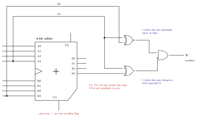
Figure 4: Two’s complement overflow detected from the pins a packaged adder actually brings out. A3 and B3 are tapped from the operand inputs and S3 from the sum output; the XNOR asks whether the two operands agree in sign and the XOR asks whether the sum disagrees with them, and overflow is both at once. C4 is deliberately left going nowhere, because the carry-out is the unsigned overflow test, not this one. The adder outline, the ‘+’ glyph and the input/output placement follow the course’s 74HCT283 schematic symbol.
There is a cheaper form still. A full adder gives \(S_3 = A_3 \oplus B_3 \oplus C_3\), so the missing internal carry can be recovered as \(C_3 = A_3 \oplus B_3 \oplus S_3\), and substituting into \(V = C_4 \oplus C_3\) leaves
\[V = C_4 \oplus A_3 \oplus B_3 \oplus S_3\]
— three two-input XOR gates, all four of which fit in a single 74HCT86.
Back to \(B - A\)
The worked example above computes \(B - A\) as \(B + \overline{A} + 1\), and it is an ordinary addition as far as the top slice is concerned — so it is the conditioned operand that the overflow test must look at. The sign bit entering the adder is \(\overline{A_{n-1}}\), not \(A_{n-1}\), which is why a subtraction of two numbers whose signs differ is the case that can overflow, while an addition of two numbers whose signs differ never can. See week2-lab-binary-arithmetic for the lab build and 2026-08-04-binary-arithmetic for the arithmetic behind the rule.
See also
- cpu-organisation · fetch-decode-execute-cycle
- binary-number-representations — two’s complement, which every subtraction row above relies on
- combinational-logic-blocks — the multiplexer and decoder used inside the slice
- 2026-08-24-alu-and-control-unit — Lecture 9