The Assembly Process
How an assembly language program becomes machine code. It covers the four fields of a statement, the directives that tell the assembler what to do as opposed to the CPU, the three memory segments of the AVR and the location counter that walks through each, and the two-pass assembler with its symbol table, which is how a program can jump to a label it has not reached yet. The program skeleton these pieces fit into is avr-program-structure, and the memories the segments map onto are in memory-models and avr-architecture. First met in 2026-10-08-assembly-process.
What an assembler does
An assembler turns a text file of assembly language into the bits that go into the chip’s memories. Most of that is translation, one statement at a time: add r1, r2 has a fixed binary form, 0000 1100 0001 0010, and nothing else in the file can change it (avr-instructions). Each instruction becomes exactly one machine instruction (instruction-set-architecture).
Two things make it more than a lookup table:
- A program is more than instructions. It has to say where things go in memory, reserve space for variables, put constant tables in flash and give registers and addresses readable names. None of that is an instruction for the CPU. These lines are directives, commands to the assembler itself.
- Names stand for numbers that are not known yet.
jmp RESETneeds the address ofRESET, and ifRESET:is further down the file, a single read from top to bottom cannot supply it. The cure is to read the file twice.
C reaches machine code by a different road: the compiler turns one line of C into many instructions (2026-09-07-introduction-to-embedded-c-programming), and how that output is joined into a program is compilation-and-linking.
The format of a statement
An assembly program is a sequence of one-line statements. A statement has up to four fields, and any of them may be empty:
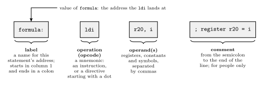
Figure 1: The four fields of one assembly statement. The label names the address this statement ends up at, so other statements can jump to it or refer to the data there. The operation field holds the mnemonic, which is either an instruction for the CPU or, if it starts with a dot, a directive for the assembler. The operands are what the operation works on: registers, constants or symbols, separated by commas. The comment runs from the semicolon to the end of the line and is thrown away by the assembler.
Label. A name for a position in memory. Labels exist so that statements can be jumped to and so that data can be referred to by name. Its value is the address the statement lands at: a word address in program memory for code, a byte address in data memory for a variable. By convention a label starts in column 1 and everything else is indented, so labels stand out down the left edge. In AVR assembly it ends with a colon.
Operation. A symbolic abbreviation for an instruction’s opcode, a mnemonic: LDS for Load Direct from data Space, ldi for load immediate. Or a directive, which starts with a dot.
Operands. The registers and addresses the instruction uses. Register names belong to the machine:
| Machine | Register names |
|---|---|
| Pentium | eax, ebx, esi, edi, … |
| SPARC | o0..o7, i0..i7, l0..l7, g0..g7 (out, in, local and global) |
| AVR | simply r0..r31 |
An address operand is usually written as a label, lds r16, count, and the assembler substitutes the number.
Comment. Space for explanation, only for people: the assembler discards it. In assembly comments are not optional politeness. ldi r20, 13 says nothing about why; the comment is the only place the intent is written down.
Ending a statement. Some assemblers want a semicolon at the end of every statement and others do not. AVR assembly does not: the end of the line ends the statement, and a semicolon starts a comment.
Directives
Besides instructions, the assembler needs other information, for example:
- where in memory the code and data should go;
- nicer names for registers and addresses, such as
tempforr16orSPHfor I/O address0x3E; - space for variables and tables of constants.
That information is given as a directive, also called a pseudo-instruction: a command to the assembler itself, written where an instruction would be and preceded by a dot, as in .byte or .def temp = r16. Most directives produce no machine code at all. They change what the assembler knows or where it is putting things.
The assembler in Microchip Studio, AVRASM2, has these, among others:
| Directive | What it does |
|---|---|
.byte |
reserve bytes for a variable |
.cseg |
switch to the code segment |
.csegsize |
set the program memory size |
.db |
define constant byte(s) |
.def |
give a register a symbolic name |
.device |
name the exact processor the program is for |
.dseg |
switch to the data segment |
.dw |
define constant word(s) |
.equ |
set a symbol equal to an expression, permanently |
.eseg |
switch to the EEPROM segment |
.exit |
stop processing this file |
.include |
read source from another file, here |
.list, .nolist |
turn generation of the list file on, off |
.listmac |
show macro expansions in the list file |
.macro, .endm (or .endmacro) |
begin, end a macro |
.org |
set the location counter: the address of what comes next |
.set |
set a symbol equal to an expression, changeably |
.if, .else, .elif, .endif |
conditional assembly: include lines only if a condition holds |
All of this is AVRASM2’s syntax. Other assemblers, even ones for the AVR, spell things differently. The GNU assembler used behind avr-gcc has a .byte directive too, and there it stores the bytes listed instead of reserving space.
Segments and location counters
The AVR has three memories (avr-architecture), and to the assembler each is a segment. Directives choose which segment the following lines go into:
| Segment | Directive | Memory | What can go there |
|---|---|---|---|
| code | .cseg |
flash, program memory | instructions, and constant data |
| data | .dseg |
SRAM, data memory | space only, reserved for variables |
| EEPROM | .eseg |
EEPROM | constants |
The data segment cannot be given values. The assembler’s output is programmed into flash and EEPROM, which keep their contents with the power off. SRAM is empty at power-up and holds nothing until the running program writes to it, so all the assembler can do there is decide which addresses each variable will use.
Each segment has its own location counter: the address the next thing in that segment will be placed at. A label takes the current value of its segment’s counter, and every statement that places something advances the counter by its size. Switching segment does not reset anything. It only changes which counter is in use, so a segment can be built up in pieces, and each piece carries on where the last piece of the same segment stopped.
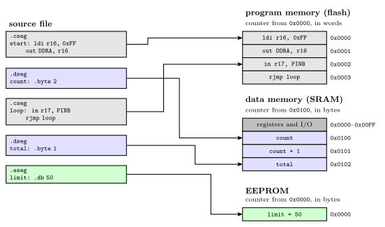
Figure 2: One source file feeding three memories. The file switches segment four times, and each piece goes to the memory its directive names, carrying on from where the previous piece of the same segment stopped: the second code piece follows the first in flash, and total follows count in SRAM. Each segment has its own location counter. The code counter starts at 0 and counts 16-bit words. The data counter starts at 0x0100, the first address after the registers and I/O, and counts bytes. The EEPROM counter starts at 0 and counts bytes. Grey marks code, blue data and green EEPROM.
Where each counter starts:
- Code: at 0, the reset address, and the assembler starts in the code segment, so a file with no segment directives is all code. The counter counts 16-bit words, because each program-memory address names a word (memory-models).
- Data: at the first free SRAM address,
0x0100on the ATmega324A, since0x0000to0x00FFare the registers and I/O registers. The counter counts bytes. - EEPROM: at 0, counting bytes.
.org sets the counter of the current segment to a given value, so whatever follows is placed there. It works in any segment, in that segment’s units.
Reserving and defining data
Three directives put data in memory:
| Directive | Segment | Places | Size |
|---|---|---|---|
.byte n |
data | nothing: reserves n bytes |
n bytes |
.db a, b, … |
code or EEPROM | constant bytes, 8 bits each | one byte each |
.dw a, b, … |
code or EEPROM | constant words, 16 bits each | two bytes each |
.byte is allowed only in the data segment: it is how a variable gets an address. .db and .dw initialise constants, so they belong where constants can live: the code segment or the EEPROM segment.
.db in the code segment packs two bytes per word. Program memory is 16 bits wide, so consecutive bytes share a word, the first in the low byte and the second in the high byte. A .db line with an odd number of bytes leaves half a word over, and the assembler fills it with a zero pad byte so that the next line starts on a whole word. Each .db line is padded on its own, so two 5-byte lines take 3 words each, not 5 words between them. AVRASM2 warns when it pads. Writing the 0 yourself gives the same layout without the warning.
.dw takes one whole word per value, so it is the natural way to store numbers bigger than 255, or addresses.
Worked: a lookup table in flash
A lookup table (LUT) is a table of constants a program reads instead of computing. Lay out:
        .cseg
table1: .db  11, 12, 30
table2: .dw  100, 133
        .org 500
table3: .dw  ...
The code counter starts at 0.
table1= 0. Three bytes: 11 and 12 share word 0, 30 takes the low half of word 1, and a pad 0 fills its high half. The counter moves to 2.table2= 2. Two words, 100 at word 2 and 133 at word 3. The counter moves to 4..org 500sets the counter to 500. Words 4 to 499 are skipped, and nothing is placed there.table3= 500 (0x01F4).
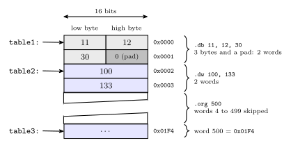
Figure 3: The lookup table laid out in program memory, one 16-bit word per row, lowest address at the top. A .db puts two bytes in each word, the first in the low byte, and pads an odd count with a zero byte so that the next label starts on a whole word: here 30 shares word 1 with a pad. Each .dw value fills a whole word. The .org moves the location counter forward and leaves words 4 to 499 untouched, so table3 lands at word 500. The diagonal break means the gap is not drawn to scale. Grey marks the .db bytes, dark grey the pad and blue the .dw words.
On the data side, two .byte 2 lines in separate .dseg pieces end up next to each other, at 0x0100 and 0x0102, whatever code sits between them in the file. That is worked in 2026-10-08-assembly-process.
Naming things: .def, .equ and .set
Three directives give a name to something. None of them places anything or moves a location counter.
| Directive | Names | Can it be changed later? | Example |
|---|---|---|---|
.def |
a register, and only a register | yes, by another .def |
.def ZH = r31 |
.equ |
a value: a number, an I/O address, an expression | no | .equ sreg = 0x3f ; Status register |
.set |
a value | yes, by another .set |
.set io_offset = 0x23 ; For now |
.equ is the usual choice for a constant, because a second definition is an error and catches a clash of names. .set is for a value that a later part of the file deliberately redefines, which is what for now in the comment above says.
Check. The same program defines .equ SPH = $3E and .def ZH = r31. Why .equ for one and .def for the other? SPH is an I/O register, which instructions such as out reach by its I/O address, 0x3E. To the assembler that is just a number, so .equ. ZH is general-purpose register r31, the high byte of the Z pointer, which instructions name as a register operand, so .def.
Two more directives are about files and the processor rather than names:
.include "file"reads another file in at that point, as if its text were typed there..include "m324Adef.inc"is howPORTA,SPH,RAMENDand the rest get defined: the file is mostly.equand.deflines (avr-io-ports)..device ATmega324Anames the exact processor. The assembler then rejects any instruction that chip does not implement..exitstops reading the file at that line. Anything after it is ignored.
The forward reference problem
Read top to bottom, most statements can be translated on the spot. add r1, r2 names two registers and nothing else, so its machine word is known at once.
A label used before it is defined is different. A program usually starts with
        jmp  RESET
        ...
RESET:  ldi  temp, low(RAMEND)
When the assembler reaches the jmp, it knows the opcode but not the operand: RESET has not been seen, so there is no address to put in the instruction. This is the forward reference problem. One forward reference anywhere in a file is enough to stop a single top-to-bottom pass from finishing the job.
The two-pass assembler
The fix is to process the file twice.
Pass one: define every symbol. Go through the file without generating anything. Keep a location counter for each segment, starting at 0 for code and EEPROM and at 0x0100 for data. For each line:
- if it has a label, enter the label in the symbol table with its segment and the current value of that segment’s counter;
- if it is
.equ,.setor.def, enter that name and its value; - if it is
.cseg,.dsegor.eseg, switch counters; if it is.org, set the current counter; - advance the current counter by the line’s size: 1 or 2 words for an instruction, the padded number of words for
.db, a word per value for.dw,nbytes for.byte n, and 0 for a line that only names something.
Pass one only needs each line’s size, and every instruction’s size is known without knowing its operands: jmp RESET takes 2 words whatever RESET turns out to be.
Pass two: assemble. Go through the file again with the counters reset. Now every symbol’s value is in the table, so each instruction can be assembled, turned into actual machine code, with its operands filled in, and each .db and .dw value can be written.
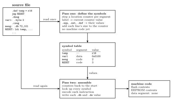
Figure 4: The two-pass assembler. Pass one reads the whole source and produces no code: it steps the location counters and records each symbol’s segment and value in the symbol table. Pass two reads the same source again from the top and, with every value now in the table, encodes each instruction and writes each constant. Its output is the contents of flash and of EEPROM. The data segment produces no output, only the addresses its labels were given.
Worked: a two-pass trace
The program:
        .equ    RAMEND = $08FF
        .equ    SPH = $3E
        .equ    SPL = $3D
        .def    ZH = r31
        .def    ZL = r30
        jmp     RESET
        .dseg
var1:   .byte   2
var2:   .byte   2
        .cseg
        .def    temp = r16
mesg:   .db     72,101,108,108,111
table:  .dw     var1, var2
RESET:  ldi     temp, low(RAMEND)
        out     SPL, temp
        ldi     temp, high(RAMEND)
        out     SPH, temp
        ...
        ldi     ZH, high(mesg*2)
        ldi     ZL, low(mesg*2)
        lpm                     ;R0 <= M[Z]
Pass one. The code counter starts at 0 and the data counter at 0x0100 (256).
- The five
.equand.deflines enterRAMEND,SPH,SPL,ZHandZLin the table and place nothing. jmp RESETis a 2-word instruction, so it takes words 0 and 1 and the code counter goes to 2.RESETis not known yet, and pass one does not need it to be..dsegswitches to the data counter.var1= 256 (0x0100) and.byte 2moves the counter to 258.var2= 258 (0x0102) and the counter goes to 260..csegswitches back to the code counter, still at 2..def temp = r16enterstemp.mesg= 2. Five bytes need three words with a pad, words 2 to 4, and the counter goes to 5.table= 5. Two words, 5 and 6, and the counter goes to 7.RESET= 7. Each of the four instructions from here is one word:ldiat 7,outat 8,ldiat 9,outat 10.
The counters run code 0, 2, 5, 7, 8, 9, 10, 11 and data 256, 258, 260. The EEPROM counter is never used.
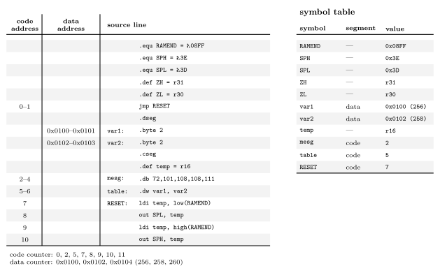
Figure 5: Pass one over the example, line by line. The two address columns show where each line is placed in its own segment, so a range means the line takes several words or bytes: the jmp two words, the 5-byte .db three words with its pad, the .dw two words, each .byte 2 two bytes. Lines that only name something or switch segment take no space and have no address. The code and data counters advance independently, which is why mesg comes straight after the jmp even though the data lines sit between them in the file. On the right is the symbol table pass one leaves behind: every name, the segment its value belongs to, and the value. The .equ and .def names have no segment.
So the instruction at RESET is at program address 7, mesg is at 2, table at 5, and the variables at 256 and 258.
Only one reference in the program is forward: jmp RESET. Every other symbol (RAMEND, var1, var2, mesg, SPL, SPH, ZH, ZL, temp) is defined above the line that uses it. One is enough to need the second pass.
Worked: what pass two writes
With the table complete, pass two replaces every symbol by its value and encodes:
| Address | Statement | With symbols replaced | Machine word(s) |
|---|---|---|---|
| 0–1 | jmp RESET |
jmp 7 |
0x940C 0x0007 |
| 2–4 | .db 72,101,108,108,111 |
bytes 72, 101, 108, 108, 111 and a pad 0 | 0x6548 0x6C6C 0x006F |
| 5–6 | .dw var1, var2 |
.dw 0x0100, 0x0102 |
0x0100 0x0102 |
| 7 | ldi temp, low(RAMEND) |
ldi r16, 0xFF |
0xEF0F |
| 8 | out SPL, temp |
out 0x3D, r16 |
0xBF0D |
| 9 | ldi temp, high(RAMEND) |
ldi r16, 0x08 |
0xE008 |
| 10 | out SPH, temp |
out 0x3E, r16 |
0xBF0E |
| later | ldi ZH, high(mesg*2) |
ldi r31, 0x00 |
0xE0F0 |
| later | ldi ZL, low(mesg*2) |
ldi r30, 0x04 |
0xE0E4 |
| later | lpm |
lpm |
0x95C8 |
Points worth checking by hand:
ldi r16, 0xFF. The form is1110 KKKK dddd KKKK, withddddthe register number minus 16.K=1111 1111anddddd=0000, so1110 1111 0000 1111=0xEF0F.- The
.dbwords. The first byte of each pair is the low byte: 72 and 101 make0x6548. The odd fifth byte, 111 =0x6F, shares its word with the pad. low()andhigh()split a 16-bit value into its bytes at assembly time.RAMEND=0x08FFgives0xFFand0x08: this is the stack pointer being set to the top of SRAM (procedures-and-the-stack).mesg*2.mesgis a word address, 2.lpmreads one byte of program memory from the byte address in Z, and word 2 starts at byte 4. So Z =0x0004, andlpmloadsr0with the byte there, 72, theHofHello. The two kinds of address are drawn in memory-models.tableholds the two variables’ addresses,0x0100and0x0102: a table of pointers, in flash, into the data segment.
Common mistakes
- Counting
jmpas one word. It is two, because it carries a full program address (avr-branches-and-jumps).rjmpis one. - Forgetting the pad. A
.dbline with an odd number of bytes takes a whole extra word, and each line is padded separately. - Counting
.dbbytes as words. Two bytes share a word in program memory. - Letting
.dseglines move the code counter, or the other way round. Each segment has its own counter, and switching segments only chooses which one is in use. - Giving size to lines that only name things.
.equ,.set,.def,.cseg,.dseg,.includeand comments place nothing. - Expecting
.byteto store a value..byte 2reserves two bytes. It does not put a 2 anywhere. Constants go in flash or EEPROM with.dbor.dw. .deffor a constant, or.equfor a register..defis for registers only.- Redefining an
.equ. It cannot be changed; that is what.setis for. - Handing a code label straight to
lpm. A code label is a word address.lpmwants the byte address, the label times 2. - Ending statements with a semicolon out of habit from another language. In AVR assembly it starts a comment.
- Assuming another assembler reads the same way. Directive names and meanings change between assemblers, even for the same chip.
See also
- avr-program-structure — the skeleton: vector table,
RESET, the main loop, and where segments and directives go in it - memory-models — word and byte addresses, cell sizes, and the AVR’s separate address spaces
- avr-architecture — flash, SRAM and EEPROM, the three memories behind the three segments · memory-technologies — what each of the three is as a technology
- avr-instructions · avr-branches-and-jumps — instruction sizes, which decide how far the code counter moves
- avr-interrupts —
.orgplacing eachjmpin the vector table - procedures-and-the-stack — the stack pointer set-up the worked example starts with
- instruction-set-architecture — assembly as a level, one line to one instruction
- compilation-and-linking — the road to machine code from C
- 2026-10-08-assembly-process — Lecture 20