AVR Interrupts
How the ATmega324A implements interrupts, and how to write one and switch it on, in assembly and in C: the path from a device’s request to the handler and back, the vector table, the switches that decide whether a request is taken, the ISR template and its stack, ISR() and the _vect names, volatile, priority, and a complete timer-interrupt program. First met in 2026-09-21-interrupts. What an interrupt is on any CPU (polling versus interrupts, the fourteen-step sequence, transparency, nesting) is polling-and-interrupts.
The path of an interrupt
An interrupt is a procedure call the hardware makes (procedures-and-the-stack). The CPU finishes the instruction in progress, pushes the address of the next one, turns interrupts off and loads the PC with the address of the vector table entry for the source. The entry holds a jmp to the handler. The handler ends with reti, which pops the return address and turns interrupts back on.
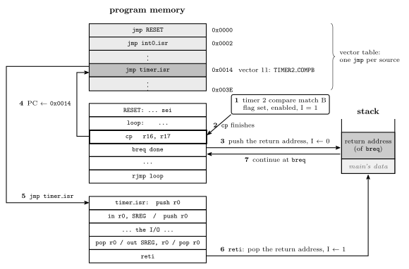
Figure 1: One timer interrupt from start to finish. The request (1) arrives while cp is executing, and the CPU lets it finish (2): an AVR instruction is never abandoned halfway. The hardware then pushes the address of the next instruction, breq, clears the I bit (3), and loads the PC with 0x0014 (4), the vector table entry for Timer/Counter 2 compare match B. The jmp stored there reaches the handler (5), which saves what it uses, does its work, restores, and ends with reti (6). That pops the return address and sets I again, and execution continues at breq (7) as if nothing had happened. It will, provided the handler restored the status register, because breq is about to read the Z flag that cp set. Nothing in the main program refers to the handler; the vector table is the only link between them.
The vector table
The first addresses of program memory hold the interrupt vector table: one entry per interrupt source, in a fixed order, each a two-word jmp to that source’s handler (avr-branches-and-jumps). The AVR uses a table of jump instructions, not a table of addresses. When it takes an interrupt it loads the PC with the address of the entry itself and executes what it finds there. So:
\[\text{entry address} = 2 \times (\text{vector} - 1)\]
RESET is vector 1, at 0x0000. A reset is taken through the same table as an interrupt, which is why every program begins with jmp RESET (avr-program-structure). The table has 31 entries on the ATmega324A and ends at 0x003C, so the program proper starts at 0x003E.
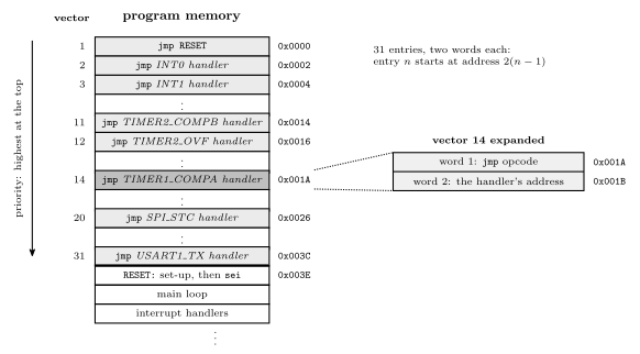
Figure 2: The bottom of program memory. Each vector-table entry is two words, the two halves of a jmp, so entry \(n\) sits at address \(2(n-1)\), and the table’s order is also its priority order: when two requests are waiting, the one nearer the top is taken first. The expanded entry shows what one of them holds, taking vector 14, Timer/Counter 1 compare match A, as the example. An entry for a source the program does not use can hold anything, as long as that interrupt is never enabled. The program itself starts at the first address after the table, which the jmp in entry 1 reaches at reset.
The full table for the ATmega324A, from pages 69–70 of the datasheet. The Group column sorts the sources by kind: GPIO, T/C, Comms, analog and system. The C name is the Source followed by _vect.
| Vector | Address | Source | Interrupt definition | Group | C handler |
|---|---|---|---|---|---|
| 1 | 0x0000 |
RESET |
RESET, watchdog reset, etc. | — | — (the program’s start) |
| 2 | 0x0002 |
INT0 |
External Interrupt Request 0 | GPIO | ISR(INT0_vect) |
| 3 | 0x0004 |
INT1 |
External Interrupt Request 1 | GPIO | ISR(INT1_vect) |
| 4 | 0x0006 |
INT2 |
External Interrupt Request 2 | GPIO | ISR(INT2_vect) |
| 5 | 0x0008 |
PCINT0 |
Pin Change Interrupt Request 0 (port A) | GPIO | ISR(PCINT0_vect) |
| 6 | 0x000A |
PCINT1 |
Pin Change Interrupt Request 1 (port B) | GPIO | ISR(PCINT1_vect) |
| 7 | 0x000C |
PCINT2 |
Pin Change Interrupt Request 2 (port C) | GPIO | ISR(PCINT2_vect) |
| 8 | 0x000E |
PCINT3 |
Pin Change Interrupt Request 3 (port D) | GPIO | ISR(PCINT3_vect) |
| 9 | 0x0010 |
WDT |
Watchdog Time-out Interrupt | system | ISR(WDT_vect) |
| 10 | 0x0012 |
TIMER2_COMPA |
Timer/Counter2 Compare Match A | T/C | ISR(TIMER2_COMPA_vect) |
| 11 | 0x0014 |
TIMER2_COMPB |
Timer/Counter2 Compare Match B | T/C | ISR(TIMER2_COMPB_vect) |
| 12 | 0x0016 |
TIMER2_OVF |
Timer/Counter2 Overflow | T/C | ISR(TIMER2_OVF_vect) |
| 13 | 0x0018 |
TIMER1_CAPT |
Timer/Counter1 Capture Event | T/C | ISR(TIMER1_CAPT_vect) |
| 14 | 0x001A |
TIMER1_COMPA |
Timer/Counter1 Compare Match A | T/C | ISR(TIMER1_COMPA_vect) |
| 15 | 0x001C |
TIMER1_COMPB |
Timer/Counter1 Compare Match B | T/C | ISR(TIMER1_COMPB_vect) |
| 16 | 0x001E |
TIMER1_OVF |
Timer/Counter1 Overflow | T/C | ISR(TIMER1_OVF_vect) |
| 17 | 0x0020 |
TIMER0_COMPA |
Timer/Counter0 Compare Match A | T/C | ISR(TIMER0_COMPA_vect) |
| 18 | 0x0022 |
TIMER0_COMPB |
Timer/Counter0 Compare Match B | T/C | ISR(TIMER0_COMPB_vect) |
| 19 | 0x0024 |
TIMER0_OVF |
Timer/Counter0 Overflow | T/C | ISR(TIMER0_OVF_vect) |
| 20 | 0x0026 |
SPI_STC |
SPI Serial Transfer Complete | Comms | ISR(SPI_STC_vect) |
| 21 | 0x0028 |
USART0_RX |
USART0 Receive Complete | Comms | ISR(USART0_RX_vect) |
| 22 | 0x002A |
USART0_UDRE |
USART0 Data Register Empty | Comms | ISR(USART0_UDRE_vect) |
| 23 | 0x002C |
USART0_TX |
USART0 Transmit Complete | Comms | ISR(USART0_TX_vect) |
| 24 | 0x002E |
ANALOG_COMP |
Analog Comparator | analog | ISR(ANALOG_COMP_vect) |
| 25 | 0x0030 |
ADC |
ADC Conversion Complete | analog | ISR(ADC_vect) |
| 26 | 0x0032 |
EE_READY |
EEPROM Ready | system | ISR(EE_READY_vect) |
| 27 | 0x0034 |
TWI |
2-wire Serial Interface | Comms | ISR(TWI_vect) |
| 28 | 0x0036 |
SPM_READY |
Store Program Memory Ready | system | ISR(SPM_READY_vect) |
| 29 | 0x0038 |
USART1_RX |
USART1 Receive Complete | Comms | ISR(USART1_RX_vect) |
| 30 | 0x003A |
USART1_UDRE |
USART1 Data Register Empty | Comms | ISR(USART1_UDRE_vect) |
| 31 | 0x003C |
USART1_TX |
USART1 Transmit Complete | Comms | ISR(USART1_TX_vect) |
Every timer event the course uses has its own vector. The three units’ compare matches and overflows are vectors 10–19, and a unit’s compare A and compare B are separate sources with separate handlers, just as they have separate flags (avr-timers-and-counters).
When a request is taken
Four things have to be true before a source’s handler runs. The four setup steps (set up the conditions, enable the interrupt, clear its flag, enable globally) arrange for them:
- The conditions for the interrupt are set up, so that the event can happen at all: a timer running in the right mode, or a pin configured to sense an edge.
- That particular interrupt is enabled, by its own bit in an I/O register. There is one bit per source.
- Its flag is set. The hardware does this when the event occurs, whether or not the interrupt is enabled. That is why the third setup step clears the flag before the interrupt is enabled: afterwards only a fresh event can set it, and an event from before the setup does not fire at once. Clearing is done by writing a 1 to the flag’s bit.
- Interrupts are enabled globally: the I bit of the status register is 1.
sei(orsei()in C) sets it.
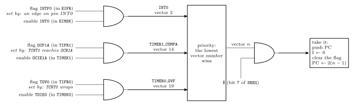
Figure 3: Whether a request becomes an interrupt, drawn as the logic it amounts to. Each source has a flag, set by its event, and an enable bit, set by the program. The source requests an interrupt only while both are 1, and all three sources here are gated the same way. If more than one is requesting, the lowest vector number wins. The winner is taken only if the I bit is also 1, and taking it clears I. For these sources, taking the vector also clears the flag. So a flag with its enable bit off simply stays set, available to be polled, and a flag that goes up while I is 0 waits and is taken the moment I returns to 1.
For the sources the course meets, the bits are:
| Source | Flag (register) | Enable (register) | Conditions set up in |
|---|---|---|---|
INT0 (pin PD2) |
INTF0 (EIFR) |
INT0 (EIMSK) |
EICRA: bits ISC01, ISC00 choose low level 00, any change 01, falling edge 10 or rising edge 11 |
TIMER0_COMPA |
OCF0A (TIFR0) |
OCIE0A (TIMSK0) |
TCCR0A, TCCR0B, OCR0A |
TIMER0_OVF |
TOV0 (TIFR0) |
TOIE0 (TIMSK0) |
TCCR0A, TCCR0B |
TIMER1_COMPA |
OCF1A (TIFR1) |
OCIE1A (TIMSK1) |
TCCR1A, TCCR1B, OCR1A |
TIMER1_OVF |
TOV1 (TIFR1) |
TOIE1 (TIMSK1) |
TCCR1A, TCCR1B |
The naming pattern is regular: an F for the flag and an IE for interrupt enable, with OC for output compare and TOV/TOIE for timer overflow. Each of these flags is cleared automatically when its vector is taken, so a handler does not normally clear its own flag. A program that polls a flag instead, with the interrupt left disabled, must clear it itself (avr-timers-and-counters).
The I bit
| I | Also | |
|---|---|---|
sei |
← 1 | |
cli |
← 0 | |
| taking an interrupt (hardware) | ← 0 | pushes PC, loads the vector address |
reti |
← 1 | pops PC |
I is bit 7 of SREG (avr-architecture), and it is 0 after reset, so no interrupt happens until the program executes sei. Because the hardware clears it on entry, a handler runs with interrupts off unless it turns them back on itself.
External interrupts
An external interrupt is requested by a pin. The ATmega324A has three, each fixed to one pin:
| Interrupt | Pin |
|---|---|
INT0 |
PD2 |
INT1 |
PD3 |
INT2 |
PB2 |
What the pin has to do to make a request is chosen by two sense control bits per interrupt, in EICRA:
ISCn1:0 |
A request is made |
|---|---|
00 |
for as long as the pin is low |
01 |
on any change of the pin |
10 |
on a falling edge, 1 to 0 |
11 |
on a rising edge, 0 to 1 |
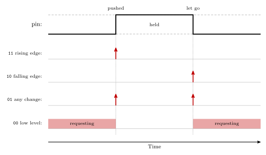
Figure 4: What each sense control setting responds to, for a push button that reads 1 while it is held. A rising edge is the moment the button is pushed and a falling edge is the moment it is let go. Any change gives a request at both. The low level setting is different in kind: it asks for the whole time the pin is low, so the handler runs again and again until the pin goes high.
Setting one up follows the same steps as any other interrupt. For a rising edge on INT0 and a falling edge on INT1:
ISR(INT0_vect) { /* PD2 went from 0 to 1 */ }
ISR(INT1_vect) { /* PD3 went from 1 to 0 */ }

/* in main */
EICRA = (1<<ISC01) | (1<<ISC00) | (1<<ISC11);   /* INT0 rising, INT1 falling */
EIMSK = (1<<INT0) | (1<<INT1);                  /* enable both               */
EIFR  = (1<<INTF0) | (1<<INTF1);                /* clear both flags          */
sei();- Edges fit buttons. An edge happens once per push, however long the button is held. That makes an external interrupt a natural way to act on a push or on a release without the program having to remember what the button was doing last time.
- Bounce. A mechanical contact chatters for a moment as it closes, and each chatter is an edge. One push can then run the handler several times.
- The low level setting keeps asking. If the pin is still low when the handler returns, the interrupt is taken again straight away.
- Priority.
INT0,INT1andINT2are vectors 2, 3 and 4, directly after reset, so they come before every timer and serial interrupt.
Used for the start/stop and reset buttons of a stopwatch in week9-lab-avr-interrupts.
Writing an ISR in assembly
The template:
isr_label:
    push r0              ; save r0: it is about to carry SREG
    in   r0, SREG
    push r0              ; save the interrupted program's flags

    ; ... perform the operation, usually input/output ...
    ; (any other register used: push it here, pop it below)

    pop  r0
    out  SREG, r0        ; flags back as they were
    pop  r0              ; r0 back as it was
    reti                 ; pop PC and set I
SREG cannot be pushed directly, because push takes a general-purpose register. So one register carries it, and that register is saved first. The restore is the save in reverse. Two consequences follow from where the save happens:
- The flags saved are the interrupted program’s. Apart from I, the hardware does not touch them on entry, and
pushchanges none, so the copy is exactly what the interrupted code left. - The saved I bit is 0, because the hardware cleared it before the first instruction of the ISR. Writing the copy back therefore leaves interrupts off until
reti, which is the right moment for them to come back.
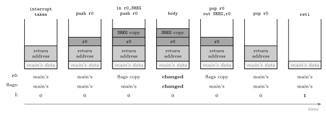
Figure 5: The stack through the ISR template, with the three things the interrupted program relies on (r0, its flags, and the I bit) traced underneath. The hardware’s push of the return address comes first, then the template’s two pushes, the SREG copy on top. The body is free to change r0 and the flags because both are safely on the stack. The restore pops the copy into r0 and writes it to SREG, then pops r0’s own value. When reti runs, the return address is on top again, exactly as the hardware left it. I stays 0 from entry to reti, the copy in the middle included, and it is reti that sets it.
Which registers to save is decided by what the body does. Save any register the body writes. Save SREG if any instruction in the body changes a flag, which rules in arithmetic, logic, compares and shifts but not in, out, ldi, mov, push or pop (avr-instructions). A handler that only copies a port to another port needs one register and no SREG at all (worked in 2026-09-21-interrupts).
Placing the entry in the table
The template in avr-program-structure puts jmp RESET at 0x0000 and leaves a comment where the handlers go. Once a vector is used, its jmp has to sit at exactly that vector’s address. The assembler’s .org directive sets the address of whatever comes next (assembly-process):
.include "m324Adef.inc"

.org 0x0000
        jmp  RESET
.org 0x001A              ; vector 14: TIMER1_COMPA
        jmp  timer1_compa_isr
.org 0x003E              ; first address after the table
RESET:
        ; stack pointer, ports, timer 1, TIMSK1 ...
        sei
loop:
        ; ...
        rjmp loop

timer1_compa_isr:
        push r0
        in   r0, SREG
        push r0
        ; ...
        pop  r0
        out  SREG, r0
        pop  r0
        reti
An assembly program that uses interrupts must also set up the stack pointer before the first sei (procedures-and-the-stack), since taking an interrupt pushes the return address.
Writing an ISR in C
#include <avr/interrupt.h>

ISR(INT0_vect) {
    /* code here */
}
ISR is a macro from avr/interrupt.h, and its argument names the vector: the source name from the datasheet followed by _vect (the table above). From it the compiler does everything the assembly programmer does by hand. The vector table is set up automatically: the handler’s jmp goes in the right entry. Registers are saved and restored automatically, SREG included, and the function ends in reti. What ISR() does not do is any of the four setup steps. In C, as in assembly, the program still sets up the conditions, enables the interrupt, clears its flag and calls sei(). sei() and cli() are macros for the single instructions.
A complete example
Timer 1 in CTC mode, matching eight times a second, with the handler toggling an LED and counting ticks. The timer set-up is Lab 12’s (week8-lab-avr-timers): \(8\,\text{MHz} / (64 \times 15625) = 8\ \text{Hz}\).
#include <avr/io.h>
#include <avr/interrupt.h>

volatile uint8_t ticks = 0;            /* written by the ISR, read by main */

ISR(TIMER1_COMPA_vect) {
    PORTA ^= (1<<0);                    /* toggle the LED on PA0 */
    ticks++;
}

int main(void) {
    DDRA = (1<<0);                      /* PA0 is an output */

    /* 1. conditions: CTC mode, clock/64, match at 15624 */
    OCR1A  = 15624;
    TCCR1A = 0;
    TCCR1B = (1<<WGM12) | (1<<CS11) | (1<<CS10);

    /* 2 and 3. clear any stale match, then enable this interrupt */
    TIFR1  = (1<<OCF1A);
    TIMSK1 = (1<<OCIE1A);

    /* 4. enable interrupts globally */
    sei();

    while (1) {
        if (ticks >= 8) {               /* a second has gone by */
            ticks = 0;
            /* ... once-a-second work ... */
        }
        /* ... anything else: the LED keeps time by itself ... */
    }
}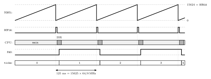
Figure 6: The example program running, one trace per signal. The count climbs to OCR1A = 15624 and is cleared (CTC mode), once every 125 ms. Each match sets OCF1A; the interrupt is enabled and I is 1, so the vector is taken a few cycles later, and taking it clears the flag again. The handler is a sliver of time in which the LED output is toggled and ticks counted, and the rest of the time belongs to main. Nothing in main looks at the timer. The LED blinks at 4 Hz, one toggle per match, however busy main is.
Priority
Priority is determined by vector: the lowest vector is the highest priority. RESET is highest, then INT0, and so on down the table. On the AVR, priority only matters when two or more interrupts are waiting to be serviced, and it decides which is taken first. It never lets one interrupt cut into another’s handler, because I is 0 throughout a handler. The datasheet adds one rule: after reti, the CPU always executes one instruction of the interrupted program before taking the next waiting interrupt, so a stream of interrupts can slow main down but never stop it altogether.
Interrupts can be re-enabled inside a handler with sei. Any incoming or waiting interrupt may then be serviced immediately, nested inside the current handler, even if it has lower priority. Priority plays no part there. Both cases are traced in 2026-09-21-interrupts and set against true priority nesting in polling-and-interrupts.
Pitfalls
- Forgetting
sei(). Everything else is set up, and nothing ever happens, because I is 0 from reset. - Enabling an interrupt that has no handler. In C, avr-libc fills every unused vector with a jump to a default handler that jumps to address 0, so the program restarts whenever the event occurs. It is not a true reset: the I/O registers keep whatever they held, which can make the restart behave differently from a power-up.
- Misspelling the vector name.
ISR(TIMER1_COMPA_Vect)compiles with only a warning, and the handler is never placed in the table, which makes it the previous pitfall. - Not clearing a stale flag before enabling: the interrupt fires once immediately, for an event that happened before the program was ready.
- Clearing a flag with
|=. If the compiler turns it into a read, an OR and a write, it clears every flag in the register that happens to be set (avr-timers-and-counters). Writing just the one bit,TIFR1 = (1<<OCF1A);, is safe however it is compiled. - In assembly: not saving
SREG, unbalanced pushes and pops, orretinstead ofreti. The first corrupts the interrupted code’s flags. The second returns to the wrong address. The third returns correctly but leaves I at 0, so no interrupt ever happens again. - Long handlers. No delay loops and no waiting inside an ISR: every other interrupt waits too, and repeated events of one source merge into one.
- A shared variable without
volatile, or a multi-byte one read withoutcli().
See also
- polling-and-interrupts — polling versus interrupts, the fourteen-step sequence, transparency, nesting policies, traps
- 2026-09-21-interrupts — Lecture 17: the stack revisited, worked questions,
volatiledrawn, priority traced - avr-timers-and-counters — the timer interrupt registers
TIMSKnandTIFRn, and the flags these interrupts replace polling - procedures-and-the-stack — the stack the return address goes on, and initialising
SP - avr-program-structure — the
jmp RESETtemplate the vector table extends - avr-architecture —
SREGand its I bit · avr-instructions — which instructions change the flags - c-preprocessor-and-avr-headers —
volatilein the I/O register macros · bit-masking —(1<<OCIE1A) - week8-lab-avr-timers — Lab 12, the timer set-up the example uses
- week9-lab-avr-interrupts — Lab 14: a stopwatch from a timer interrupt and two external interrupts
- software-timers — one timer interrupt keeping time for the whole program
- avr-usart — the three serial interrupts · analog-to-digital-conversion — the conversion-complete interrupt · avr-spi — the transfer-complete interrupt