Lab 14 — AVR Interrupts
Learning Lab 14: interrupts in C, used to build a stopwatch. A timer interrupt every 10 ms keeps the time, and two push buttons start, stop and reset it. The lab has a preparation task, which is to design the stopwatch’s controller as a state machine and to work out the timer values. The ideas are in avr-interrupts, polling-and-interrupts, software-timers and state-machines.
The stopwatch
- The two-digit seven-segment display shows the elapsed time in seconds and tenths, from 0.0 up to 9.9, and then wraps round to 0.0.
- There are two push buttons: S, start/stop, and R, reset.
- Start/stop takes effect when S is pushed.
- Reset takes effect when R is released.
Preparation: the controller
The controller is a Moore machine (state-machines). Its inputs are the two buttons and it has three outputs, written as three bits in the order C T D:
| State | C T D | C: clear the count | T: the count advances | D: the time is displayed |
|---|---|---|---|---|
| RESET | 100 |
yes | no | no |
| RUN | 011 |
no | yes | yes |
| STOP | 001 |
no | no | yes |
D is 0 only in RESET, so taken literally the display is blank until the stopwatch is first started, and blank again after each reset. The programs below do exactly that. To show 0.0 in RESET instead, light the display in every state.
There are many right answers. A design is checked against four questions:
- Does it do what was asked?
- Does it deal with a button being pushed and then released? Start/stop acts on the push, reset on the release.
- What happens while a button is held down? Nothing more should.
- What if both buttons are down at once, and then let go in either order?
With edges as inputs
The simplest design takes its inputs as events: S is “the start/stop button has just been pushed” and R is “the reset button has just been released”. Three states are enough.
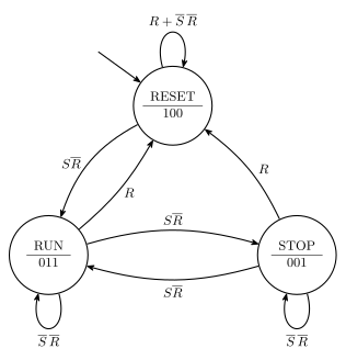
Figure 1: The stopwatch controller when its inputs are edges: S is a push of start/stop and R is a release of reset. Each state shows its name over its outputs C T D. A push of S starts the count from RESET, and after that alternates between RUN and STOP. A release of R returns to RESET from anywhere, and R is written alone on those arrows because it wins if both events arrive together. With nothing happening every state loops back to itself.
Against the four questions:
- Pushed and released. Only one edge of each button is an input, so the other edge does nothing. Letting go of S is not an event, and neither is pushing R.
- Held down. A held button produces no more edges, so nothing more happens.
- Both at once. With both buttons held, nothing happens. Letting go of R resets, whether S is still down or not, and letting go of S is not an event. If a push of S and a release of R arrive in the same step, the arrows for S are labelled \(S\overline{R}\) and the arrows for R are labelled \(R\) alone, so the reset wins.
This is the design that fits interrupts, because an edge on a pin is exactly what an external interrupt reports.
With levels as inputs
If R is instead the level of the reset button, 1 for as long as it is down, the machine has to do the waiting itself. Going straight to RESET when R becomes 1 would reset on the push. So each of RUN and STOP gets a partner state that means “reset is being held”, and the move to RESET happens when R goes back to 0.
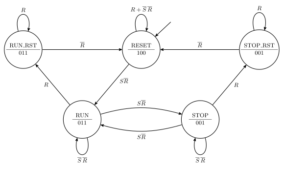
Figure 2: The controller when R is the level of the reset button, 1 while it is held down. Two states are added. While reset is held the machine waits in RUN_RST or STOP_RST, with the same outputs as the state it came from, so the stopwatch carries on exactly as it was. Only when the button is let go does it move to RESET. S has to be a single push of start/stop, 1 for one step, and it is ignored for as long as R is 1.
- Reset on release. RUN to RUN_RST on \(R\), wait there while \(R\) stays 1, then RUN_RST to RESET on \(\overline{R}\). The same from STOP.
- Held down. RUN_RST and STOP_RST loop on \(R\) for as long as the button is held, and the stopwatch does not change in the meantime: a running count keeps running.
- Both at once. From RUN or STOP, \(R\) takes priority over \(S\). In the waiting states S is not looked at. Whichever order the buttons are let go in, the machine arrives in RESET with nothing pending.
For this to work S has to be an event, 1 for a single step when the button goes down. If S were a raw level too, holding it would flip between RUN and STOP on every step, and it would need waiting states of its own.
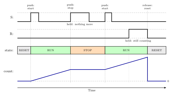
Figure 3: One run of the stopwatch. The count starts at the moment S is pushed and not when it is let go, and each later push of S stops or restarts it. Holding S down for a long time does nothing extra. When R is pushed the count carries on, and the stopwatch clears only at the moment R is let go. In the design with levels as inputs, the stretch where R is held is the waiting state RUN_RST, which has the same outputs as RUN.
Preparation: timer 1 for a 10 ms tick
The stopwatch needs something to happen 100 times a second. Timer/counter 1 does it with a compare match A every 10 ms:
- divide the 8 MHz clock by 8, so the timer counts at 1 MHz;
- clear the count on the compare match (CTC mode), so the match comes round at a steady rate;
- leave the output pins alone.
What goes in OCR1A? From the master formula (avr-timers-and-counters):
\[100 = \frac{8\,000\,000}{8 \times (OCR1A + 1)} \quad\Longrightarrow\quad OCR1A + 1 = 10\,000 \quad\Longrightarrow\quad OCR1A = \mathbf{9999}\]
The register is 16 bits, held as two bytes OCR1AH and OCR1AL. In C it is written as one 16-bit value and the compiler splits it.
What goes in TCCR1A and TCCR1B? Pages 136 to 139 of the datasheet.
| Setting | Bits | |
|---|---|---|
| no output pins | COM1A1:0 = 00, COM1B1:0 = 00 |
all 0 in TCCR1A |
CTC, top in OCR1A |
WGM13:0 = 0100 |
WGM12 in TCCR1B. The other three are 0 |
| clock / 8 | CS12:0 = 010 |
CS11 in TCCR1B |
OCR1A  = 9999;
TCCR1A = 0;
TCCR1B = (1<<WGM12) | (1<<CS11);
Interrupts in C
The global switch. The I bit, bit 7 of the status register SREG, turns all interrupts on or off together. sei() sets it and cli() clears it. In assembly the same two are the instructions sei and cli.
Setting an interrupt up takes five things:
- Set the conditions for the interrupt, such as a timer’s mode and compare value, or which edge of a pin.
- Enable that interrupt by setting its bit in the mask register.
- Clear its flag, in case it is already set from before. A flag is cleared by writing a 1 to it.
- Have a handler for it.
- Turn interrupts on globally with
sei().
The handler is a function with no arguments and no return value, written with the ISR macro:
#include <avr/interrupt.h>

ISR(INT0_vect) {
    /* code that runs when the interrupt happens */
}
The name in the brackets is the interrupt’s source name from the vector table (pages 69 to 70 of the datasheet) with _vect on the end: INT0_vect, TIMER1_COMPA_vect, and ADC_vect for the end of an analog conversion. The full list is in the avr-libc documentation for <avr/interrupt.h>.
The compiler does the rest. In C there is no vector table to write and no registers to save by hand. ISR puts the handler’s address in the table, and the compiled handler saves the registers it uses on the way in and restores them on the way out.
Handlers must be short. While one runs, everything else waits, other interrupts included. A handler records what happened and returns. Printing in a handler is far too slow. The stopwatch’s tick handler does a little more than count, since it also lights the next display digit, but both jobs together take well under a thousand clock cycles out of the 80 000 between ticks.
Shared variables are volatile. A variable that a handler changes and the main program reads must be declared volatile, as in volatile uint8_t count;. Without it the compiler may assume the variable cannot change behind the main program’s back and never read it again (avr-interrupts).
Three checks
What is the handler for timer/counter 1’s compare match A called? The source name in the vector table is TIMER1_COMPA, so the handler is ISR(TIMER1_COMPA_vect).
Of these interrupts, which has the highest priority? TIMER0_COMPA, TIMER0_COMPB, TIMER1_COMPA, TIMER1_COMPB, TIMER2_COMPA, TIMER2_COMPB, USART0_RX, USART0_TX.
Priority goes by position in the vector table, lowest vector number first:
| Source | Vector |
|---|---|
TIMER2_COMPA |
10 |
TIMER2_COMPB |
11 |
TIMER1_COMPA |
14 |
TIMER1_COMPB |
15 |
TIMER0_COMPA |
17 |
TIMER0_COMPB |
18 |
USART0_RX |
21 |
USART0_TX |
23 |
So TIMER2_COMPA. The trap is to expect timer 0 to come first. The table lists the timers in the order 2, 1, 0.
Which pin is INT1? PD3. INT0 is PD2, next to it.
Two worked set-ups
A timer compare match
To run a handler on every compare match A of timer/counter 1:
ISR(TIMER1_COMPA_vect) {
    /* runs on every compare match A */
}

/* in main */
OCR1A  = 9999;                          /* 1: the conditions              */
TCCR1A = 0;
TCCR1B = (1<<WGM12) | (1<<CS11);
TIMSK1 = (1<<OCIE1A);                   /* 2: enable (bit 1 of TIMSK1)    */
TIFR1  = (1<<OCF1A);                    /* 3: clear the flag by writing 1 */
sei();                                  /* 5: interrupts on               */
TIMSK1 is on page 142 of the datasheet and TIFR1 on page 143.
An external interrupt on a rising edge
To run a handler whenever pin INT0 (PD2) goes from 0 to 1:
ISR(INT0_vect) {
    /* runs on every rising edge of PD2 */
}

/* in main */
EICRA = (1<<ISC01) | (1<<ISC00);        /* 1: rising edge                 */
EIMSK = (1<<INT0);                      /* 2: enable                      */
EIFR  = (1<<INTF0);                     /* 3: clear the flag by writing 1 */
sei();                                  /* 5: interrupts on               */
The sense control bits in EICRA choose what counts as a request (avr-interrupts):
ISCn1:0 |
A request is made |
|---|---|
00 |
for as long as the pin is low |
01 |
on any change of the pin |
10 |
on a falling edge |
11 |
on a rising edge |
These registers are on pages 75 and 76 of the datasheet. The register diagrams there label the bits IINT0 and IINTF0, which is a misprint. The names are INT0 and INTF0.
One timer, many timings
Three timer/counters are not enough if each timed thing gets one to itself. A software timer gets round it. One timer interrupt at a fixed interval adds 1 to a global count of the time since reset, and everything else reads that count. Copying the count into a local variable marks the moment something happened, and subtracting two such copies gives a duration, in units of the interrupt period. Code built this way never has to sit in a delay doing nothing (software-timers).
The stopwatch is a first step towards it. Its time is a count of 10 ms ticks, advanced by the tick handler only while the stopwatch is running.
The tasks
- Start from
lab14-1.c.- Fill in the code where indicated, using the register values worked out above.
- Add the controller code from the state diagram.
- Compile and simulate. Put a breakpoint in the handler and make sure it is reached, and check the cycle counter is what it should be.
- Check that it works on the board.
- Start from
lab14-2.c. Make start/stop a push button on an external interrupt: a rising edge onINT0(pin D2). Set up the edge, enable the interrupt and clear the flag. Compile, simulate, download and test. - Add a reset button: an interrupt on the falling edge of
INT1(pin D3). - Extension: after 9.9 s, show whole seconds (10, 11, 12, and so on) instead of wrapping round.
Working — Exercise 1
lab14-1.c and lab14-2.c come with gaps to fill in. These are complete programs that do the job, to compare against.
Wiring. The seven-segment display is on port A with its digit select CC on PD0, as in Lab 12. Start/stop is on PD2 and reset on PD3, which are the pins the later exercises need. The buttons read 1 while pressed.
The design. The timer handler runs every 10 ms. It advances the count while the stopwatch is running and lights one of the two digits. The main loop is the controller of Figure 2. It reads the buttons as levels once per tick, steps the state machine, and sets the three outputs from the state.
#include <avr/io.h>
#include <avr/interrupt.h>

/* controller states */
#define RESET     0
#define RUN       1
#define STOP      2
#define RUN_RST   3       /* running, reset button held */
#define STOP_RST  4       /* stopped, reset button held */

uint8_t seven_seg[10] = { 63,6,91,79,102,109,125,7,127,111 };

/* shared between main and the handler, so all volatile */
volatile uint16_t count;       /* elapsed time, in hundredths of a second */
volatile uint8_t  timing;      /* T: the count advances while this is 1   */
volatile uint8_t  showing;     /* D: the digits are lit while this is 1   */
volatile uint8_t  tick;        /* set by the handler every 10 ms          */

/* runs 100 times a second */
ISR(TIMER1_COMPA_vect) {
    static uint8_t left = 0;
    uint8_t tenths;

    if (timing) {
        count++;
        if (count == 1000) {            /* 9.99 s rolls over to 0.00 */
            count = 0;
        }
    }

    /* one digit per tick: seconds on the left, tenths on the right */
    tenths = count / 10;                /* 0 to 99 */
    left = !left;
    if (!showing) {
        PORTA = 0;
    } else if (left) {
        PORTA = seven_seg[tenths / 10] | 0x80;     /* with the decimal point */
        PORTD |= (1<<0);
    } else {
        PORTA = seven_seg[tenths % 10];
        PORTD &= ~(1<<0);
    }

    tick = 1;
}

int main(void) {
    uint8_t state = RESET;
    uint8_t s, r, s_before = 0, pushed;

    DDRA = 0xFF;                        /* segments                        */
    DDRD = (1<<0);                      /* CC out; PD2 (S) and PD3 (R) in  */

    /* timer 1: compare match A every 10 ms */
    OCR1A  = 9999;
    TCCR1A = 0;
    TCCR1B = (1<<WGM12) | (1<<CS11);

    TIMSK1 = (1<<OCIE1A);               /* enable the compare match A interrupt */
    TIFR1  = (1<<OCF1A);                /* clear its flag by writing 1          */
    sei();                              /* interrupts on                        */

    while (1) {
        if (tick) {                     /* once per 10 ms */
            tick = 0;

            s = (PIND >> 2) & 1;
            r = (PIND >> 3) & 1;
            pushed = s && !s_before;    /* S has gone down since the last tick */
            s_before = s;

            /* next state */
            switch (state) {
            case RESET:
                if (pushed && !r) { state = RUN; }
                break;
            case RUN:
                if (r)           { state = RUN_RST; }
                else if (pushed) { state = STOP; }
                break;
            case STOP:
                if (r)           { state = STOP_RST; }
                else if (pushed) { state = RUN; }
                break;
            case RUN_RST:
            case STOP_RST:
                if (!r) { state = RESET; }
                break;
            }

            /* outputs: they depend on the state alone */
            timing  = (state == RUN || state == RUN_RST);     /* T */
            showing = (state != RESET);                       /* D */
            if (state == RESET) {                             /* C */
                cli();
                count = 0;
                sei();
            }
        }
    }
}
How the code follows the diagram.
- One
caseper state, oneifper arrow. Testingrbeforepushedis what makes reset win when both happen together. A state’s loop back to itself is the case where noiffires. - S as an event.
PINDgives the level of the button, 1 on every pass while it is held. The diagram wants a push. Comparing each reading with the one before,s && !s_before, is true only on the pass where the reading goes from 0 to 1. - R as a level.
ris used as it is read, and the two waiting states turn the level into “act on the release”. - Outputs from the state.
timing,showingand the clearing ofcountare set fromstateand nothing else, which is what makes it a Moore machine. cli()aroundcount = 0.countis 16 bits, and an 8-bit processor writes it one byte at a time. Turning interrupts off for those two instructions keeps the handler from running in between and seeing half of the old value with half of the new (software-timers).- Reading the buttons once per tick also deals with contact bounce. A button’s contacts chatter for a few milliseconds as they close. With readings 10 ms apart, at most one of them can land in the chatter, so a push is still seen as a single change from 0 to 1.
In the simulator. Put a breakpoint on the first line of the handler and run. Each time the program stops there, the cycle counter should have advanced by 80 000, which is 10 ms at 8 MHz. If the breakpoint is never reached, one of the five set-up steps is missing. If the interval is wrong, check OCR1A and the prescaler bits.
Working — Exercises 2 and 3
With the buttons on external interrupts the hardware finds the edges, so the controller becomes the three-state machine of Figure 1 and each button’s handler is one of its inputs.
#include <avr/io.h>
#include <avr/interrupt.h>

#define RESET  0
#define RUN    1
#define STOP   2

uint8_t seven_seg[10] = { 63,6,91,79,102,109,125,7,127,111 };

volatile uint16_t count;              /* hundredths of a second */
volatile uint8_t  state = RESET;

/* every 10 ms */
ISR(TIMER1_COMPA_vect) {
    static uint8_t left = 0;
    uint8_t tenths;

    if (state == RUN) {               /* T */
        count++;
        if (count == 1000) {
            count = 0;
        }
    }

    tenths = count / 10;
    left = !left;
    if (state == RESET) {             /* D is 0 */
        PORTA = 0;
    } else if (left) {
        PORTA = seven_seg[tenths / 10] | 0x80;
        PORTD |= (1<<0);
    } else {
        PORTA = seven_seg[tenths % 10];
        PORTD &= ~(1<<0);
    }
}

/* Exercise 2. Start/stop: a rising edge on INT0 (PD2), the push */
ISR(INT0_vect) {
    if (state == RUN) {
        state = STOP;
    } else {
        state = RUN;                  /* from RESET or from STOP */
    }
}

/* Exercise 3. Reset: a falling edge on INT1 (PD3), the release */
ISR(INT1_vect) {
    state = RESET;
    count = 0;                        /* C */
}

int main(void) {
    DDRA = 0xFF;
    DDRD = (1<<0);

    OCR1A  = 9999;
    TCCR1A = 0;
    TCCR1B = (1<<WGM12) | (1<<CS11);
    TIMSK1 = (1<<OCIE1A);
    TIFR1  = (1<<OCF1A);

    /* INT0 on a rising edge  (ISC01:0 = 11)
       INT1 on a falling edge (ISC11:0 = 10) */
    EICRA = (1<<ISC01) | (1<<ISC00) | (1<<ISC11);
    EIMSK = (1<<INT0) | (1<<INT1);
    EIFR  = (1<<INTF0) | (1<<INTF1);

    sei();

    while (1) {
        /* nothing to do: the handlers do all the work */
    }
}
For Exercise 2 on its own, leave out the INT1 handler and the ISC11, INT1 and INTF1 bits.
Points to notice.
- The main loop is empty. Nothing polls the buttons. The processor is only interrupted when something happens.
- Push and release come from the edge chosen. Start/stop uses the rising edge, so it acts as the button goes down. Reset uses the falling edge, so it acts as the button comes up. Holding either one down produces no further edges, and so no further interrupts.
- No
cli()roundcount = 0this time. Inside a handler interrupts are already off, so the timer handler cannot run in the middle of it. - Both at once. If both flags are set together,
INT0has the lower vector and runs first, thenINT1runs and resets. Reset wins, as the diagram says it should. - Why these two pins.
INT0andINT1are fixed to PD2 and PD3. The buttons have to be wired there. - Bounce shows up here. An edge interrupt responds to every edge, and a bouncing contact makes several, in both directions. A bouncing push of S can start and stop the stopwatch at once, and so can a bouncing release, which makes rising edges too. A bouncing push of R makes falling edges, so the reset can happen on the push instead of the release. A cure is to keep a count of ticks that never stops (software-timers) and ignore an edge that comes within a few ticks of the last one on the same button.
Working — Exercise 4
To carry on past 9.9 s, the count has to run further and the display has to change what it shows. count is in hundredths of a second and is 16 bits wide, so it can go up to 99.99 s without any change of type.
In the timer handler, let the count run to 100 seconds:
    if (state == RUN) {
        count++;
        if (count == 10000) {          /* 99.99 s rolls over to 0.00 */
            count = 0;
        }
    }
and choose the two digits by range. This replaces tenths and the two lines that use it:
    uint8_t l, r;

    if (count < 1000) {                /* under 10 s: seconds and tenths */
        l = seven_seg[count / 100] | 0x80;
        r = seven_seg[(count / 10) % 10];
    } else {                           /* 10 s and over: whole seconds   */
        l = seven_seg[count / 1000];
        r = seven_seg[(count / 100) % 10];
    }

    left = !left;
    if (state == RESET) {
        PORTA = 0;
    } else if (left) {
        PORTA = l;
        PORTD |= (1<<0);
    } else {
        PORTA = r;
        PORTD &= ~(1<<0);
    }
count |
Time | Left digit | Right digit | Shows |
|---|---|---|---|---|
| 0 | 0.00 s | count / 100 = 0, with point |
(count / 10) % 10 = 0 |
0.0 |
| 990 | 9.90 s | 9, with point | 9 | 9.9 |
| 1000 | 10.00 s | count / 1000 = 1 |
(count / 100) % 10 = 0 |
10 |
| 1234 | 12.34 s | 1 | 2 | 12 |
| 9999 | 99.99 s | 9 | 9 | 99 |
The decimal point is what tells the two ranges apart on the display: 9.9 is followed by 10.
See also
- avr-interrupts — the vector table, flags and masks, handlers in C,
volatile, priority, external interrupts - polling-and-interrupts — why interrupts, and what the processor does when one arrives
- software-timers — one timer interrupt, many timings, and no busy waiting
- avr-timers-and-counters — CTC mode and the master formula
- state-machines — Moore machines and state diagrams
- week9-lab-avr-pwm — Lab 13
- week10-lab-adc-and-spi — Lab 16: the A/D converter and the SPI port
- week8-lab-avr-timers — Lab 12: display multiplexing
- 2026-09-21-interrupts — Lecture 17
- seven-segment-display · c-preprocessor-and-avr-headers