Lab 13 — AVR PWM
Learning Lab 13: generating pulse width modulation from the timer/counters. Two programs come out of it. The first fades two LEDs with timer/counter 0, and the second plays a tone on a piezo buzzer with timer/counter 1, with push buttons changing its pitch and its duty cycle. The lab assumes Lab 12 (week8-lab-avr-timers). The ideas are in pulse-width-modulation and avr-timers-and-counters.
Facts to have ready
Five things the lab takes for granted, as quick checks.
| Question | Answer |
|---|---|
| How many timer/counters does the ATmega324A have? | 3 |
| What is the clock frequency? | 8 MHz |
| How wide is each timer/counter? | timer 0 is 8-bit, timer 1 is 16-bit, timer 2 is 8-bit |
| What is the largest value each can hold? | timers 0 and 2: \(2^8 - 1 = 255\). Timer 1: \(2^{16} - 1 = 65535\) |
Which pin is OC0B? |
PB4 (OC0A is PB3) |
Fast PWM on timer/counter 0
The duty cycle of a waveform is the fraction of each period for which it is high. A pin toggled in CTC mode, as in Lab 12, is high for exactly half of every cycle, a duty cycle of 50 %, and nothing about it can be adjusted except the frequency. PWM is what makes the duty cycle adjustable.
In fast PWM the count, held in TCNT0, is a sawtooth: it climbs from 0 to a top value and drops back to 0. An output-compare register sets a level somewhere on the ramp. The output pin changes where the count crosses that level, and changes back when the count wraps. Moving the level moves the crossing, and that changes how much of each period the pin is high.
The waveform generation mode bits choose among all of a timer’s modes: normal, CTC and the PWM modes. Timer 0 has two fast PWM modes:
WGM02:0 |
Top of the count | Compare registers free for PWM | Frequency set by |
|---|---|---|---|
011 (mode 3) |
255, fixed | OCR0A and OCR0B: two PWM outputs |
the prescaler only |
111 (mode 7) |
the value in OCR0A |
OCR0B only: one PWM output |
the prescaler and OCR0A |
Four things apply in both modes:
- The waveform appears on the output-compare pin only if that pin’s DDR bit is set to make it an output.
- The output can be non-inverting or inverting, chosen by the compare output mode bits.
- The prescaler sets how fast the count climbs, and so the slope of the ramp.
- The output-compare registers are double buffered. A new value written to one does not take effect until the next cycle begins, so a pulse is never cut short halfway through.
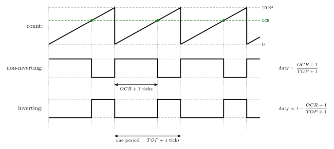
Figure 1: Fast PWM, one compare value, both polarities. The count ramps from 0 to TOP and wraps. In non-inverting mode the pin is set at the wrap and cleared at the compare match, so it is high for the first \(OCR + 1\) ticks of each period. In inverting mode it is the exact opposite, low until the match and high until the wrap. The two outputs are complements, and their duty cycles add up to 1.
The two formulas
Frequency: the master formula (avr-timers-and-counters).
\[f_{event} = \frac{f_{clk\_I/O}}{N \cdot (TOP + 1)}\]
\(f_{clk\_I/O}\) is 8 MHz, \(N\) is the prescaler, and \(TOP\) is either the largest value the register can hold or the value in OCRnA, depending on the mode. What “the event” is depends on the use:
| Use | \(f_{event}\) is |
|---|---|
| a pin set to toggle | how often the pin toggles. The waveform is half that frequency, since one cycle needs a rise and a fall |
| PWM | the frequency of falling edges in non-inverting mode, and of rising edges in inverting mode. That is the PWM frequency |
| an interrupt | how often the handler runs |
Duty cycle.
\[d.c._{nin} = \frac{OCRnx + 1}{TOP + 1} \qquad\qquad d.c._{inv} = 1 - \frac{OCRnx + 1}{TOP + 1} = 1 - d.c._{nin}\]
OCRnx is the compare register for the output in question, A or B.
The two formulas pull against each other in the choice of mode:
- When TOP is
OCRnA, the frequency can be set to almost anything, butOCRnAis used up setting it. OnlyOCRnBgives a meaningful duty cycle. - When TOP is a fixed constant (
0xFFfor the 8-bit timers, with several choices for the 16-bit timer), bothOCRnAandOCRnBgive a duty cycle. But the frequency can then be changed only through the prescaler, or for timer 1 through the choice of constant.
Timer 0’s control bits
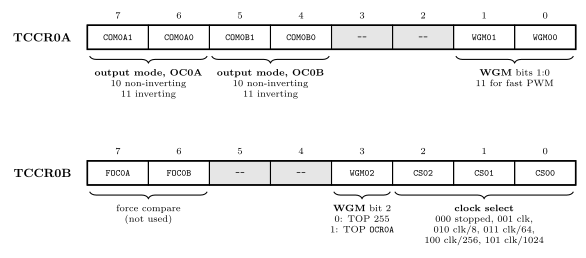
Figure 2: Where timer/counter 0’s settings live. The compare output mode bits come in two pairs, one for each output pin, and both pairs are in TCCR0A. The waveform generation mode is one three-bit number split across the two registers, with its low two bits in TCCR0A and its top bit in TCCR0B. The clock select bits choose the prescaler, and while they are 000 the timer is stopped. Grey cells are unused.
These are on pages 109 to 113 of the datasheet. Clock select 110 and 111 take the clock from the T0 pin instead of the prescaler, which is how Lab 12 counted button presses. The compare output modes in fast PWM:
COM0x1:0 |
The pin OC0x |
|---|---|
00 |
is disconnected from the timer: an ordinary port pin |
01 |
OC0A toggles at each compare match, in mode 7 only. Not used for OC0B |
10 |
non-inverting: cleared at the compare match, set at the wrap |
11 |
inverting: set at the compare match, cleared at the wrap |
Delay macros
#define F_CPU 8000000UL
#include <util/delay.h>
With these two lines, the macros _delay_ms() and _delay_us() are available. Each takes a constant number and makes the CPU do nothing for that many milliseconds or microseconds.
_delay_ms(10); /* do nothing for 10 ms */F_CPU has to be defined before the include, because the macros work out how many instructions to waste from the clock frequency. If it is missing the header only warns and assumes 1 MHz, and on this board every delay then runs 8 times too short. The macros are documented under <util/delay.h> in avr-libc.
This is busy waiting: the processor is fully occupied counting down and can do nothing else in the meantime. It is fine for a quick experiment and a bad habit for anything bigger. The alternative is a timer keeping time in the background (software-timers).
The tasks
Complete lab13-1.c so that two LEDs fade on and off using PWM, one connected to OC0A and one to OC0B.
- Work out the register values from pages 109 to 113 of the datasheet.
- Build it, download it and test it. Predict which LED starts on and which starts off.
- Change the clock prescaler to CLK/1024 and explain what you see.
Complete lab13-2.c to generate sound on the piezo buzzer using PWM on timer/counter 1.
- Connect the buzzer between
OC1Band ground, and an LED toOC1Bas well so that what is happening can be seen. - Push buttons vary both the frequency and the duty cycle.
- The code uses 32-bit constants such as
105ULin places. Why are they necessary? - Challenge: show the duty cycle, 0 to 99, on the seven-segment display.
Working — Task 1
lab13-1.c comes with gaps to fill in. This is a complete program that does the job, to compare against.
The design. Fast PWM with TOP fixed at 255 (mode 3), because two outputs are needed and the frequency does not matter much. One compare value, level, is swept slowly from 0 up to 255 and back, and written to both compare registers. OC0A is made non-inverting and OC0B inverting, so as one LED brightens the other dims.
The register values.
| Setting | Bits | Value |
|---|---|---|
| fast PWM, TOP = 255 | WGM02:0 = 011 |
WGM01, WGM00 in TCCR0A. WGM02 stays 0 |
OC0A non-inverting |
COM0A1:0 = 10 |
COM0A1 |
OC0B inverting |
COM0B1:0 = 11 |
COM0B1, COM0B0 |
| clock / 64 | CS02:0 = 011 |
CS01, CS00 in TCCR0B |
The PWM frequency is \(8\,000\,000 / (64 \times 256) = 488\ \text{Hz}\), far too fast to see.
#define F_CPU 8000000UL
#include <avr/io.h>
#include <util/delay.h>

int main(void) {
    uint8_t level = 0;      /* compare value: 0 to 255          */
    int8_t  step  = 1;      /* +1 on the way up, -1 on the way down */

    /* OC0A is PB3 and OC0B is PB4: both must be outputs */
    DDRB |= (1<<3) | (1<<4);

    /* Fast PWM with TOP = 255; OC0A non-inverting, OC0B inverting */
    TCCR0A = (1<<COM0A1) | (1<<COM0B1) | (1<<COM0B0)
           | (1<<WGM01) | (1<<WGM00);

    /* Clock / 64.  This starts the timer. */
    TCCR0B = (1<<CS01) | (1<<CS00);

    while (1) {
        OCR0A = level;
        OCR0B = level;
        _delay_ms(5);                 /* 255 steps of 5 ms: about 1.3 s each way */

        if (level == 255) {
            step = -1;
        } else if (level == 0) {
            step = 1;
        }
        level += step;
    }
}
Which LED starts on? At the start level is 0.
OC0A, non-inverting: duty \(= (0 + 1)/256 \approx 0.4\,\%\). The LED on PB3 starts off.OC0B, inverting: duty \(= 1 - 1/256 \approx 99.6\,\%\). The LED on PB4 starts on.
As level rises the first brightens and the second dims, they cross at half brightness, and at 255 they have swapped. The non-inverting output never reaches exactly 0 %: even with a compare value of 0 the pin is high for one tick in 256.
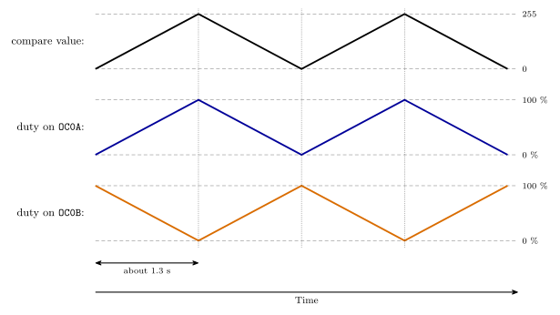
Figure 3: The fade in Task 1. The compare value is swept up from 0 to 255 and back down, about 1.3 seconds each way. The two outputs share that one value but have opposite polarity, so their duty cycles are mirror images: the LED on OC0A is brightest when the value is 255 and the LED on OC0B is brightest when it is 0. The dim end of each is one tick in 256 short of fully off.
With the prescaler at CLK/1024. Change the last register write to
TCCR0B = (1<<CS02) | (1<<CS00); /* clock / 1024 */The PWM frequency drops to \(8\,000\,000 / (1024 \times 256) = 30.5\ \text{Hz}\). The eye can follow that. The LEDs flicker instead of dimming smoothly, most obviously when the duty cycle is low and the LED is giving short flashes thirty times a second. The fade itself takes just as long as before, because _delay_ms(5) sets its speed, not the timer. The duty cycle is unchanged as well. Only the PWM frequency has changed, and this is what shows that PWM dims an LED only when it is too fast to see.
The fade also turns into steps. A PWM period is now 32.8 ms, and a new compare value only takes effect at the start of a period, so of the values written every 5 ms only about one in six or seven is ever used.
Working — Task 2
lab13-2.c also comes with gaps. This is a complete program that meets the task.
The design. A tone needs a frequency that can be set freely, so this uses a fast PWM mode in which TOP is OCR1A. That leaves OCR1B for the duty cycle, which is why the buzzer goes on OC1B. Timer 1 is 16 bits wide, so one prescaler setting covers the whole audible range.
| Setting | Bits | Where |
|---|---|---|
fast PWM, TOP = OCR1A |
WGM13:0 = 1111 (mode 15) |
WGM11, WGM10 in TCCR1A; WGM13, WGM12 in TCCR1B |
OC1B non-inverting |
COM1B1:0 = 10 |
COM1B1 in TCCR1A |
| clock / 8 | CS12:0 = 010 |
CS11 in TCCR1B |
With the prescaler at 8 the timer counts at 1 MHz, one tick per microsecond. For a tone of frequency \(f\):
\[\text{period in ticks} = \frac{1\,000\,000}{f} \qquad OCR1A = \text{period} - 1 \qquad OCR1B = \frac{\text{duty} \times \text{period}}{100} - 1\]
The first is the master formula rearranged, and the last is the duty-cycle formula rearranged, with the duty as a percentage. At 200 Hz the period is 5000 ticks, so OCR1A is 4999, and a 50 % duty cycle makes OCR1B 2499.
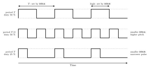
Figure 4: The two settings of Task 2 and what each one changes. OCR1A is the top of the count, so it sets the length of the period and with it the pitch. OCR1B sets how much of each period the pin is high, the duty cycle. Halving the period while keeping the duty cycle at 50 percent gives the middle waveform, an octave higher. Keeping the period and narrowing the pulse to 25 percent gives the bottom one, the same pitch with less energy.
The program. Four push buttons on port C: PC0 raises the frequency and PC1 lowers it, PC2 raises the duty cycle and PC3 lowers it. The buttons read 1 while pressed, and each press counts once.
#define F_CPU 8000000UL
#include <avr/io.h>
#include <util/delay.h>

uint16_t freq = 200;     /* Hz                      */
uint8_t  duty = 50;      /* percent, 0 to 99        */

/* Load the timer from freq and duty.  The timer counts at 1 MHz. */
void update_pwm(void) {
    uint16_t period = 1000000UL / freq;                   /* ticks per cycle */
    uint16_t width  = (duty * (uint32_t)period) / 100;    /* ticks high      */

    OCR1A = period - 1;                 /* TOP: sets the frequency           */
    if (width == 0) {
        TCCR1A &= ~(1<<COM1B1);         /* 0 %: hand the pin back to PORTD   */
    } else {
        OCR1B = width - 1;              /* high for OCR1B + 1 ticks          */
        TCCR1A |= (1<<COM1B1);
    }
}

int main(void) {
    uint8_t now, before = 0, pressed;

    DDRD |= (1<<4);                     /* OC1B is PD4                       */
    PORTD &= ~(1<<4);                   /* low whenever the timer lets go    */
    DDRC &= 0xF0;                       /* PC0 to PC3 are the buttons        */

    update_pwm();                       /* load OCR1A and OCR1B first        */

    /* Fast PWM with TOP = OCR1A (mode 15), OC1B non-inverting, clock / 8 */
    TCCR1A = (1<<COM1B1) | (1<<WGM11) | (1<<WGM10);
    TCCR1B = (1<<WGM13) | (1<<WGM12) | (1<<CS11);   /* this starts the timer */

    while (1) {
        now = PINC & 0x0F;
        pressed = now & ~before;        /* buttons that have just gone down  */
        before = now;

        if (pressed & (1<<0)) { freq = freq * 105UL / 100; }   /* up 5 %    */
        if (pressed & (1<<1)) { freq = freq * 100UL / 105; }   /* down 5 %  */
        if (pressed & (1<<2)) { duty = (duty >= 95) ? 99 : duty + 5; }
        if (pressed & (1<<3)) { duty = (duty == 99) ? 95 : (duty >= 5 ? duty - 5 : 0); }

        if (freq < 20)    { freq = 20; }
        if (freq > 10000) { freq = 10000; }

        if (pressed) {
            update_pwm();
        }
        _delay_ms(10);                  /* ride out contact bounce           */
    }
}
Why the UL constants are needed. On the AVR an int is 16 bits. In freq * 105 / 100 both operands would be 16-bit, the multiplication would be done in 16 bits, and the result would overflow as soon as freq passed \(65535 / 105 = 624\) Hz. A tone of 1000 Hz would give \(105\,000\), which wraps to 39 464, and the “5 % higher” frequency would come out as 394 Hz. Writing 105UL makes the constant an unsigned long, 32 bits, so the compiler does the whole multiplication in 32 bits and only the final result is narrowed back to 16. The suffix matters on the constants that would fit in an int, 105UL and 100UL. On 1000000UL it is harmless but not needed, since a number too big for an int is given a 32-bit type anyway. The (uint32_t) cast in the width calculation does the same job as the suffix, where duty * period can reach nearly five million (c-language-basics: an int is 16 bits on the AVR).
Other points.
- The pin still needs
DDRD. The timer decides the pin’s value. The DDR bit decides whether the pin drives anything. - Changing the values while it runs. Each compare register is double buffered: a new value is held back and loaded when the count wraps, so a pulse already under way is not disturbed. The two registers are written a few instructions apart, so at worst one period uses the new
OCR1Awith the oldOCR1B, which is one odd cycle of a tone. Disconnecting the pin for 0 % is not buffered and takes effect at once. - Load the compare registers before starting the timer.
maincallsupdate_pwm()first, so the timer never runs withOCR1Astill at 0. - 0 % is a special case. In non-inverting fast PWM the pin is high for
OCR1B + 1ticks, which is at least one. For a true 0 % the function disconnects the pin from the timer, and the port bit, set to 0, holds it low. - The lowest frequency. With the prescaler at 8, the longest period is 65 536 ticks, about 15 Hz. The program stops at 20 Hz.
- What duty cycle does to a tone. The pitch depends only on the frequency. The duty cycle changes the loudness and the character of the sound, and is loudest near 50 %. On the LED it shows as brightness.
Challenge: the duty cycle on the seven-segment display. The two-digit multiplexing of Lab 12 fits into the main loop, which already comes round every 10 ms. Show one digit per pass: the display is on port A, with the digit select CC on PD0 (seven-segment-display).
uint8_t seven_seg[10] = { 63,6,91,79,102,109,125,7,127,111 };
uint8_t left = 0;

/* in main, before the loop */
DDRA = 0xFF;
DDRD |= (1<<0);

/* in the loop, once per pass */
if (left) {
    PORTA = seven_seg[duty / 10];     /* tens  */
    PORTD |= (1<<0);                  /* CC = 1: left digit  */
} else {
    PORTA = seven_seg[duty % 10];     /* ones  */
    PORTD &= ~(1<<0);                 /* CC = 0: right digit */
}
left = !left;
Each digit is refreshed 50 times a second, which is just fast enough to look steady. Shortening the delay to 5 ms makes it more comfortable.
Next
Lab 14 has a preparation task, to be done before the session (week9-lab-avr-interrupts).
See also
- pulse-width-modulation — duty cycle, average value, the fast PWM modes and their formulas
- avr-timers-and-counters — the timers, their registers, the prescaler and the master formula
- week8-lab-avr-timers — Lab 12: the control registers bit by bit, and display multiplexing
- software-timers — keeping time without busy waiting
- 2026-09-17-pulse-width-modulation — Lecture 16
- seven-segment-display · bit-masking · c-language-basics · avr-io-ports