Seven-Segment Display
How a digit is shown on the IO board’s seven-segment display: the segment lettering, the byte that lights a pattern, the lookup table for all ten digits, and the common-cathode line that selects which of the two digits is lit. First met in 2026-09-10-more-c-programming-on-the-avr; the board’s header is in io-board and the port registers in avr-io-ports.
Segments
Seven bars lettered a to g, plus a decimal point dp:
| Segment | Position |
|---|---|
| a | top |
| b | upper right |
| c | lower right |
| d | bottom |
| e | lower left |
| f | upper left |
| g | middle |
| dp | the dot, lower right |
— clockwise from the top for a to f, then g across the middle. Each segment is an LED; a 1 on its line lights it.
The byte
The display is driven from one 8-bit port, one bit per segment, in this order:
| bit 7 | bit 6 | bit 5 | bit 4 | bit 3 | bit 2 | bit 1 | bit 0 |
|---|---|---|---|---|---|---|---|
| dp | g | f | e | d | c | b | a |
So the byte for a digit is read off by asking, segment by segment, whether it is lit. Two worked examples:
| Digit | Lit | dp g f e d c b a | Sum | Decimal |
|---|---|---|---|---|
| 0 | a b c d e f | 0 0 1 1 1 1 1 1 |
\(32 + 16 + 15\) | 63 |
| 2 | a b g e d | 0 1 0 1 1 0 1 1 |
\(64 + 16 + 8 + 3\) | 91 |
PORTA = 63; shows a 0; PORTA = 91; shows a 2. The 2 and both bytes are drawn in 2026-09-10-more-c-programming-on-the-avr.
All ten digits
The lookup table from the program below, decoded:
| Digit | Decimal | Binary (dp g f e d c b a) | Segments lit |
|---|---|---|---|
| 0 | 63 | 0011 1111 |
a b c d e f |
| 1 | 6 | 0000 0110 |
b c |
| 2 | 91 | 0101 1011 |
a b d e g |
| 3 | 79 | 0100 1111 |
a b c d g |
| 4 | 102 | 0110 0110 |
b c f g |
| 5 | 109 | 0110 1101 |
a c d f g |
| 6 | 125 | 0111 1101 |
a c d e f g |
| 7 | 7 | 0000 0111 |
a b c |
| 8 | 127 | 0111 1111 |
a b c d e f g |
| 9 | 111 | 0110 1111 |
a b c d f g |
Displays differ on whether 6 lights segment a, the top bar, and whether 9 lights segment d, the bottom bar. This table lights both, giving a hooked 6 and an underlined 9.
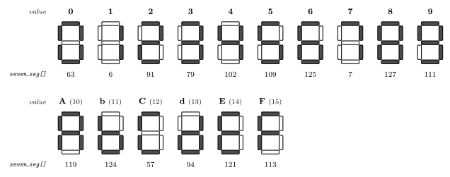
Figure 1: All sixteen values a nibble can hold, as seven-segment patterns, with the byte that produces each one in decimal underneath — the sixteen entries of the lookup table in order. Heavy segments are lit; the bit order is dp g f e d c b a with a at bit 0, so each number is read straight off the lit segments: 63 is every segment but g, 6 is b and c alone. The hex letters b and d are lowercase because their capitals would be indistinguishable from 8 and 0 on seven segments; A, C, E and F have no such clash.
Hex digits A–F
Four input bits hold 0–15, and the six values past 9 can be shown too, as hex letters. Two of them have to be lowercase: an uppercase B on seven segments is an 8, and an uppercase D is a 0.
| Value | Shows | Segments lit | dp g f e d c b a |
Decimal |
|---|---|---|---|---|
| 10 | A | a b c e f g | 0111 0111 |
119 |
| 11 | b | c d e f g | 0111 1100 |
124 |
| 12 | C | a d e f | 0011 1001 |
57 |
| 13 | d | b c d e g | 0101 1110 |
94 |
| 14 | E | a d e f g | 0111 1001 |
121 |
| 15 | F | a e f g | 0111 0001 |
113 |
With these appended the table has sixteen entries and every value a masked nibble can produce is a valid index, so the guard in the program below can go:
uint8_t seven_seg[16] = { 63,6,91,79,102,109,125,7,127,111,
                          119,124,57,94,121,113 };
This is Lab 11’s Task 2 (week8-lab-avr-c-programming), and the same table drives the hex adder of its Task 3.
The program
#include <avr/io.h>

/* Seven segment display values */
uint8_t seven_seg[10] = { 63,6,91,79,102,109,125,7,127,111};

int main(void) {
  uint8_t digit;

  /* Set port A pins to be outputs, port C pins to be inputs */
  DDRA = 0xFF;
  DDRC = 0;    /* This is the default, could omit. */
  while(1) {
    /* Read in a digit from lower half of port C pins */
    /* We read the whole byte and mask out upper bits */
    digit = PINC & 0x0F;
    /* Write out seven segment display value to port A */
    if(digit < 10) {
      PORTA = seven_seg[digit];
    } else {
      PORTA = 0;
    }
  }
}
Port A drives the eight segment lines; the low four bits of port C are the input digit. The loop reads the digit, masks off the upper nibble (bit-masking), looks the pattern up and writes it. The if guards the table — four bits can be 10–15, and seven_seg[10] is past the end of the array (c-pointers-and-arrays); those inputs blank the display instead.
Lookup table, not arithmetic. There is no formula that turns a digit into its segment pattern, so the program does not try: the ten answers are precomputed and indexed. It is the general pattern for any input-to-output mapping that is small and irregular, and it is what the array is for.
Two digits, one set of lines: CC
On the IO board the display has two digits but the header carries one set of segment pins — DP, G … A — plus one more, CC, the common cathode (io-board). The segment lines go to both digits; CC decides which one is actually lit:
CC |
Lit |
|---|---|
| 1 | left digit |
| 0 | right digit |
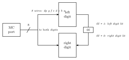
Figure 2: Why one port can drive two digits. The eight segment lines are wired to both digits in parallel, so both always receive the same pattern; the CC line selects which digit’s common cathode is connected to ground, and only that digit lights. One byte and one select bit therefore describe the whole display at any instant. To show two different digits the program alternates — left pattern with CC = 1, then right pattern with CC = 0 — fast enough that the eye sees both at once.
Writing a digit therefore takes two outputs: the segment byte on port A, and CC on whichever pin it is wired to. The program above drives a single digit and never touches CC; in Lab 11 CC is simply jumpered to a button, so pressing it moves the same digit across.
Display multiplexing
Showing a two-digit number means time-sharing the segment lines: write the tens pattern with CC = 1, wait, write the ones pattern with CC = 0, wait, repeat. Alternate fast enough — every millisecond, say — and persistence of vision merges the two into a steady two-digit display, each digit at half brightness because it is lit half the time. Slow the alternation to a few times a second and the trick becomes visible, with the digits taking turns. The waiting is a timer’s job (avr-timers-and-counters); the whole program, and a timing diagram of the two digits taking turns, is Lab 12’s Task 2 (week8-lab-avr-timers). Two things the ordering has to get right: write the segments before switching CC, so the newly selected digit never flashes the other digit’s pattern, and keep the tick regular, or one digit will look brighter than the other.
See also
- io-board — the header pins
CC DP G F E D C B A, and where the display sits on the board - avr-io-ports —
DDRA,PORTA,PINC - bit-masking —
PINC & 0x0F - c-pointers-and-arrays — the lookup table
- c-preprocessor-and-avr-headers — why
PORTAcan be assigned to - 2026-09-10-more-c-programming-on-the-avr — Lecture 14
- week8-lab-avr-c-programming — Lab 11: the display wired up, hex digits, the adder · week8-lab-avr-timers — Lab 12: display multiplexing on a timer tick · week9-lab-avr-interrupts — Lab 14: the display as a stopwatch