Lecture 14 — More C: C Programming on the AVR
This is where C meets the hardware: arrays, pointers and what they look like in the AVR’s data memory; the preprocessor and the header file that turns DDRA into a memory address; and a complete program that drives the IO board’s seven-segment display. The evergreen notes are c-pointers-and-arrays, c-preprocessor-and-avr-headers and seven-segment-display; the shift rules go into c-operators.
Bit shifts in C
The three assembly shifts are lsl, lsr and asr, from Lecture 12 (2026-09-03-instruction-set-architecture-part-2):
| Instruction | Movement of the bits | Effect |
|---|---|---|
lsl |
C ⇐ [ register ] ⇐ 0 |
× 2 |
lsr |
0 ⇒ [ register ] ⇒ C |
÷ 2 unsigned |
asr |
the top bit looped back into itself, ⇒ C |
÷ 2 signed |
The C equivalents:
a << b |
a shifted left by b bits |
a >> b |
a shifted right by b bits — a logical shift right if a is unsigned, an arithmetic shift right if a is signed |
In assembly the programmer chooses lsr or asr by hand and thereby declares what the bits mean. In C the declaration is the variable’s type, and the compiler picks the instruction: unsigned char gets lsr, char gets asr. There is one >> operator and two instructions behind it. (Strictly, the C standard leaves >> on a negative signed value implementation-defined; avr-gcc chooses the arithmetic shift, and treats plain char as signed, which is what makes the rule hold on this toolchain.)
Two more points:
1 << 5is00100000, a single 1 in bit 5. This is the idiom the AVR headers are built on: a flag is a bit number, sayFLAG_NAME == 5, and1 << FLAG_NAMEis the mask for it. The worked bits are drawn in the shift figure of 2026-09-07-introduction-to-embedded-c-programming; the idiom is in bit-masking.- Assembly to machine code is
1:1: one assembly line is one machine instruction. C also ends up as machine code, but by a route where one statement may become several instructions (the C-to-machine-code figure of 2026-09-07-introduction-to-embedded-c-programming).
Arrays in C
An array is declared as type variable_name[size];
char message[16];int values[10];float BT_26[365];— 365 entries, presumably one per day of a year.
An element is accessed as variable_name[index], where index = 0 … size−1. This is zero-based indexing.
message[0] = 'c';values[9] = values[8]++;BT_26[0] = 36.3;down toBT_26[364] = 33.8;— the first and last legal indices of a 365-element array.
BT_26[365] does not exist, and C will not stop you writing to it: it will write to whatever happens to sit after the array in memory. The memory layouts below make that concrete.
values[9] = values[8]++; is postfix, so it is two statements: values[9] = values[8]; and then values[8] = values[8] + 1; — the copy gets the old value (2026-09-07-introduction-to-embedded-c-programming).
Pointers
C has pointers. A pointer is declared as type * variable_name;, which makes variable_name a pointer to something of the given type. A pointer variable stores a memory address.
For example:
char a, b;
char *ptr;      /* can write these on one line: char a,b,*ptr; */

ptr = &a;       /* & is address-of operator - creates a pointer  */
b = *ptr;       /* * is indirection operator - returns value pointed to */
Figure 1 works it in data memory. Say a = 8, with a at address 400, b at address 434 and ptr at address 576. After the two assignments, ptr == 400 and b == 8.
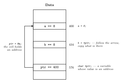
Figure 1: The pointer example in data memory. Three variables, three cells: a holds 8, b holds 8 (copied through the pointer), and ptr holds 400 — which is not a value but the address of a, hence the arrow. The decimal addresses 400, 434 and 576 are only examples; where the compiler actually places variables is its own business. The lowest address is at the top and addresses are written down the right, as in the course’s memory maps, but in decimal here.
The two operators are inverses, and Figure 1 is the way to keep them straight. &a goes from a variable to its address — the number 400. *ptr goes from an address back to the value stored there — follow the arrow, read the cell. b = *ptr; therefore lands 8 in b. ptr is itself an ordinary variable with its own cell at 576; a pointer is just a variable whose contents happen to be an address.
This is the indirect addressing mode of addressing-modes made into a language feature: ptr plays the part of X, and b = *ptr; compiles to something like ld r_b, X.
Pointers and arrays
An array name can be treated as a pointer to the first element, i.e. the address of the first element.
int a[10];
int *ptr;

/* following statements are same */
ptr = a;
ptr = &a[0];
The array is a contiguous run of cells in data memory, and its name means the address where that run starts: 300, say.
Operations on pointers
Addition and subtraction on pointers work in multiples of the size of the object being pointed to.
int a[10];
int *ptr;

/* following statements are same */
ptr = a+5;
ptr = &a[5];
An int on the AVR is 16 bits, and a data memory cell is 8 bits wide. With a at 300, a + 5 is not 300 + 5 = 305 but 300 + 2·5 = 310. In memory a[0] lies across addresses 300 and 301, a[1] across 302 and 303, and so on down to a[9]. a is 300, and so is ptr after ptr = a. Figure 2 draws it out.
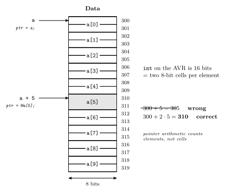
Figure 2: int a[10] in the AVR’s data memory. Each cell is 8 bits wide; an int on the AVR is 16 bits, so every element takes two cells and the array runs from 300 to 319. That is why a + 5 is address 310, not 305: pointer arithmetic counts in elements, and the compiler multiplies by the element size. The shaded element is a[5], the one the arithmetic lands on.
The compiler does the multiplication. a + 5 means five elements on, and since an int is two cells on this machine that is ten cells, so 310. Had the array been char, a + 5 would be 305 — the same source expression, a different address, decided entirely by the declared type. This is also why the rule says the size of the object being pointed to rather than a number: the number is machine-dependent, exactly as the size of int itself is (Lecture 13). See memory-models for the AVR’s 8-bit data cells, which are what make the two-cells-per-int happen.
Traversing an array
Two ways of clearing an array, each filling its cells with 0 one after another.
Using an index:
int a[10];
int index;
for(index=0; index<10; index++) {
    a[index] = 0;
}
Using a pointer:
int a[10], *ptr;
for(ptr=a; ptr < a+10; ptr++) {
    *ptr = 0;
}
ptr++ works because adding one to an array pointer makes it point to the next element in the array.
The two loops are the same loop. The index version computes a + index on every iteration and dereferences it; the pointer version keeps that address in ptr and moves it by one element — two cells — each time round. ptr < a+10 is the same bound as index < 10: the address one past the last element, which is the first address the loop must not touch. Both stop before it. The for itself is the repetition column of Lecture 13’s three-shapes figure; the anatomy is in c-control-flow.
Preprocessor
A C program is first parsed by a preprocessor, which replaces preprocessor directives with substitute text. The two directives used here are #include … and #define … (macros); there are many others, such as #if, #ifdef, #else and #undef.
Figure 3 shows #include. A file name.c has #include <header.h> at its top, the directive names a second file header.h, and the combined text is compiled to machine code (M/C).
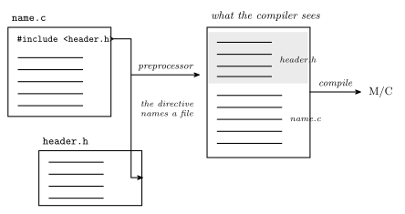
Figure 3: What #include does. The directive is not an instruction to the compiler; it is replaced, textually, by the contents of the named file before the compiler sees anything — so what gets compiled is one file, name.c with header.h pasted in at the top, drawn on the right.
Header (.h) files
Header files (.h files) hold common macros, function prototypes and so on, like m324Adef.inc for assembly (avr-io-ports).
Two examples:
stdio.h— includes the prototypes ofprintf()etc. The AVR has a simplified version of this (e.g. no files), andprintf()will only work if you specify where the characters go, e.g. sent via the serial port.avr/io.h— the AVR’s header of useful constants and functions/macros. Its definitions depend on the actual device targeted.
avr/io.h is what makes DDRA = 0xFF a legal line of C. The macro sections below explain why.
Preprocessor examples
| Form | Kind of header |
|---|---|
#include<filename.h> |
system |
#include"filename.h" |
user-defined |
Angle brackets look in the system’s include directories — where avr/io.h and stdio.h live; double quotes look in your own project first.
A macro is a textual substitution:
| Macro | Use |
|---|---|
#define pi 3.1415 |
in A = pi * r^2; the pi is replaced by 3.1415 |
#define EVER ;; |
in for(EVER) { … } the EVER is replaced by ;;, giving for( ;; ) { … } |
#define sum(a,b) (a+b) |
EVER shows the mechanism: for(EVER) is not a language feature, it is for(;;) after two semicolons have been pasted in, and for(;;) with no condition loops forever. The preprocessor does not know C. It replaces text, and only afterwards does the compiler read the result as a program.
Worked: SQUARE(1+2)
Given
#define SQUARE(x) (x*x), what is the result ofSQUARE(1+2)?
5. The substitution is literal, (1+2*1+2), and it is evaluated as written: multiplication first, so \(1 + 2 + 2 = 5\). Not 9.
The fix is to define the macro as ((x)*(x)). Then SQUARE(1+2) is ((1+2)*(1+2)) = 9. The rule: parenthesise every parameter, and the whole body, because the argument is pasted in as text and inherits whatever operators surround it. The AVR headers below are written this way for exactly this reason, with brackets around (mem_addr) and (io_addr).
AVR C macro examples
From avr/io.h (via the device-specific header it pulls in):
#define _MMIO_BYTE(mem_addr) \
                (*(volatile uint8_t *)(mem_addr))
#define _SFR_IO8(io_addr) \
                _MMIO_BYTE((io_addr) + 0x20)

/* Input Pins, Port A */
#define PINA      _SFR_IO8(0x00)

/* Data Direction Register, Port A */
#define DDRA      _SFR_IO8(0x01)

/* Data Register, Port A */
#define PORTA     _SFR_IO8(0x02)
The macros chain: DDRA is defined with _SFR_IO8, and _SFR_IO8 with _MMIO_BYTE, adding 0x20 on the way. Figure 4 unrolls the chain for DDRA = 0xFF.
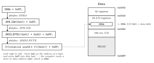
Figure 4: The macro chain behind DDRA, unrolled from the three #define lines. DDRA expands to _SFR_IO8(0x01), which expands to _MMIO_BYTE(0x21), which expands to a dereferenced pointer to data address 0x21. The + 0x20 is the offset between the I/O-space number an out instruction uses and the data-space address of the same register — the two columns of the I/O register table in the AVR I/O ports note. The memory map on the right is the datasheet’s, as in Lecture 11.
Read the innermost line from the inside out: (uint8_t *)(0x21) says treat the number 0x21 as the address of an 8-bit unsigned byte; the outer * dereferences it, so the whole expression is that byte; and = 0xFF stores into it. volatile tells the compiler the byte can change behind its back — a hardware register does — so it must not cache the value in a register or skip a store it thinks redundant.
The + 0x20 is the same fact as the two columns of the register table in avr-io-ports: the address an out instruction takes is the I/O space number, and the same register sits 0x20 higher in the data space where lds/sts — and a C pointer — reach it. DDRA is I/O 0x01, data 0x21, and the macro converts one to the other.
I/O register names as variables
The upshot of these macro definitions is that I/O register names can be used as variables:
DDRA = 0xFF;
PORTA = PINC | 0xF0;
Compare the assembly for the first (avr-io-ports): ser r16 then out DDRA, r16. The C is one line, and the compiler chooses the register. The second line is a read-modify-write across two ports — read PINC, OR in the mask, write PORTA — and the | 0xF0 is a set mask in the sense of bit-masking: the top four bits are forced to 1, the bottom four pass through from PINC.
Seven segment display programming example
Figure 5 draws the display and the byte that drives it.
The display has seven bars, lettered a across the top, b upper right, c lower right, d across the bottom, e lower left, f upper left, g across the middle, and a small circle dp for the decimal point. Setting the five segments a, b, g, e and d to 1 lights the digit 2.
The microcontroller (MC) drives the display from port A: eight wires, one per segment. The bit order is:
| bit 7 | bit 6 | bit 5 | bit 4 | bit 3 | bit 2 | bit 1 | bit 0 |
|---|---|---|---|---|---|---|---|
| dp | g | f | e | d | c | b | a |
Two worked bytes:
| Digit | dp g f e d c b a | Value | Statement |
|---|---|---|---|
| 0 | 0 0 1 1 1 1 1 1 |
\(32 + 16 + 15 = 63\) | PORTA = 63; |
| 2 | 0 1 0 1 1 0 1 1 |
\(64 + 16 + 8 + 3 = 91\) | PORTA = 91; |
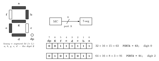
Figure 5: The seven-segment display and its byte. Left: the seven segments lettered a to g clockwise from the top with g across the middle, plus the decimal point; the segments drawn heavy are the ones set to 1, which spell a 2. Right: the byte written to port A, one bit per segment, dp at bit 7 down to a at bit 0, with two worked bytes: 63 for a 0 and 91 for the 2 on the left.
The sums read each byte in chunks: 00111111 is \(32 + 16\) for bits 5 and 4 and then \(15\) for the low nibble 1111; 01011011 is \(64 + 16 + 8\) for the three high ones and 11 \(= 3\) at the bottom. Full encoding table for all ten digits in seven-segment-display.
Seven segment display on IO board
The header pins along the board’s top edge are TX RX CC DP G F E D C B A B3 B2 B1 B0 PR. The display’s pins are CC to A; the silk-screen brackets the display pins as SSD. CC is the common cathode pin, and it selects the digit:
| left digit ON | CC = 1 |
| right digit ON | CC = 0 |
Two digits, one set of segment lines. The A–G and DP pins go to both digits; CC selects which one is actually lit. So a two-digit number is shown by alternating — drive the left digit’s segments with CC high, then the right digit’s with CC low, fast enough that both look steady. The header itself is in io-board.
The program
#include <avr/io.h>

/* Seven segment display values */
uint8_t seven_seg[10] = { 63,6,91,79,102,109,125,7,127,111};

int main(void) {
  uint8_t digit;

  /* Set port A pins to be outputs, port C pins to be inputs */
  DDRA = 0xFF;
  DDRC = 0;    /* This is the default, could omit. */
  while(1) {
    /* Read in a digit from lower half of port C pins */
    /* We read the whole byte and mask out upper bits */
    digit = PINC & 0x0F;
    /* Write out seven segment display value to port A */
    if(digit < 10) {
      PORTA = seven_seg[digit];
    } else {
      PORTA = 0;
    }
  }
}
Everything above is in this one listing:
#include <avr/io.h>— angle brackets, a system header; it is what makesDDRA,DDRC,PINCandPORTAlegal names, anduint8_ttoo.uint8_t seven_seg[10] = { … }— an array, declared with its ten values in braces, outsidemainso it is not one ofmain’s locals. Its index is the digit, its contents the byte from Figure 5: the first three values, 63, 6 and 91, are the digits 0, 1 and 2, andseven_seg[0]andseven_seg[2]are the two bytes worked above.uint8_tis the header’s name for an unsigned 8-bit integer —unsigned charwith its size written on it.DDRA = 0xFF; DDRC = 0;— direction registers, port A all outputs, port C all inputs, exactly as in week6-lab-avr-io-ports but without theldi/outpairs.while(1)— the repetition column of Lecture 13’s three-shapes figure with a condition that is always true. An embedded program has nowhere to return to, so itsmainnever finishes; every AVR program from here on has this loop.digit = PINC & 0x0F;— read the input port, keep the low nibble: bit-masking, the extract case, in C.if(digit < 10)— selection, guarding the array: indices 10–15 are possible from four input bits andseven_seg[10]does not exist. Theelseblanks the display instead of reading past the end of the array.
See also
- c-pointers-and-arrays — arrays, pointers, pointer arithmetic and traversal
- c-preprocessor-and-avr-headers —
#include,#define, the macro pitfalls and_SFR_IO8 - seven-segment-display — the segment layout, all ten codes, and the two-digit
CCtrick - c-operators —
>>on signed and unsigned, and1 << n - c-control-flow —
for,while(1)and theifguard - 2026-09-07-introduction-to-embedded-c-programming — Lecture 13
- avr-io-ports · bit-masking · memory-models · addressing-modes · io-board