Pulse Width Modulation
Pulse width modulation (PWM): making a digital output behave like an adjustable analog one by switching it on and off quickly and controlling what fraction of the time it is on. What the duty cycle is, why a fast pulse train has an average value, what that is good for, and how the AVR’s timer/counters generate it in hardware in their two fast PWM modes. From 2026-09-17-pulse-width-modulation; the timers themselves are in avr-timers-and-counters.
Duty cycle
A PWM signal is a periodic pulse — high for part of each period, low for the rest — and it is described by two numbers:
| Period \(T\) (s), or equivalently the frequency \(f = 1/T\) (Hz) | how often the pulse repeats |
| On-time \(T_{ON}\) (s) | how long the output is high in each period |
\[\text{duty cycle} = \frac{T_{ON}}{T} \times 100\%\]
The duty cycle is the percentage of the time the signal is on (high). 0 % is a constant low, 100 % a constant high, 50 % a square wave; modulating the pulse width means changing \(T_{ON}\) while \(T\) stays fixed. The five duty cycles are drawn in 2026-09-17-pulse-width-modulation.
Average value
If the pulses are fast enough, the signal looks like its average. The average of a periodic voltage is the area under one period divided by the period, and for a pulse between 0 and \(V\) the area is a rectangle:
\[V_{avg} = \frac{1}{T}\int_0^{T} v(t)\,dt = \frac{1}{T}\int_0^{T_{ON}} V\,dt = V \cdot \frac{T_{ON}}{T}\]
so the average voltage is the supply voltage times the duty cycle — 1.25 V at 25 % of 5 V, 2.5 V at 50 %. That is the whole point: a pin that can only ever be at 0 V or 5 V delivers, on average, any voltage between, set by a number in a register.
Fast enough means fast compared with the load. A motor’s inertia, a lamp’s thermal mass, the eye’s persistence or an explicit low-pass filter each smooth the pulses into their average; if the period is long enough for the load to follow the pulses, it sees pulses. So the frequency is chosen for the load once, and the duty cycle is the only thing varied afterwards.
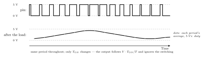
Figure 1: A PWM signal and what a slow load makes of it. Above, the pin’s actual voltage: pulses at a fixed period whose width steps up and then down. Below, the same signal after a low-pass filter — a motor’s inertia, an LED as the eye sees it, or a real RC network before a speaker — which cannot follow individual pulses and settles at their running average. The filtered output tracks the duty cycle and not the pulses, with a small ripple left over from the switching, and moving the duty cycle from period to period moves the output smoothly: an analog waveform out of a digital pin. The higher the PWM frequency relative to the load’s response, the smaller the ripple.
What it is for
Generating signals that look analog from a purely digital source. The AVR has no digital-to-analog converter, and PWM plus the load’s own smoothing is how it gets an analog-looking output:
- Varying the brightness of lights and LEDs — fading is ramping the duty cycle; the eye averages
- Motor control — the average voltage sets the speed of a DC motor; the inertia averages
- Generating audio, with appropriate filtering — vary the width from period to period so the average traces a waveform, filter off the pulses, and what is left is the tone
PWM on the AVR: fast PWM
A timer/counter (avr-timers-and-counters) generates PWM with no software involvement at all. The mechanism is the same in every mode: the count is a sawtooth, a compare register draws a horizontal line across it, and the pin changes state where they cross — once at the match and once more when the count wraps. Moving the compare value moves the crossing along the ramp, which moves one edge of the pulse. That is the modulation.
The waveform generation mode bits pick what the top of the sawtooth is, and the compare output mode bits pick which way the pin switches at the crossing.
Mode 3 — top fixed at 255 (WGM[2:0] = 011)
The count runs 0 to 255 and wraps: every period is exactly 256 ticks, so
\[T_{tick} = \frac{1}{CLK/PRE} \qquad T = \frac{256}{CLK/PRE} \qquad f = \frac{CLK}{256 \cdot PRE}\]
and the frequency is set entirely by the prescaler. Both compare registers are free to make pulses, so one timer gives two independent PWM outputs at the same frequency, OCnA and OCnB. With the compare value at 191 the pin is high for 64 of the 256 ticks in inverting mode, a 25 % duty cycle — the worked example in 2026-09-17-pulse-width-modulation.
Mode 7 — top in OCRnA (WGM[2:0] = 111)
The count wraps when it reaches OCRnA instead of 255: the period is OCRnA + 1 ticks and can be chosen,
\[T = \frac{1 + OCRnA}{CLK/PRE} \qquad f = \frac{CLK}{(1 + OCRnA) \cdot PRE}\]
The pulse is then made on the other compare unit, OCRnB against the shorter ramp. The price of choosing the frequency is that compare unit A is spent on it: one PWM output per timer, and OCnA can at most toggle on each wrap. With OCRnA = 127 and OCRnB = 95 the period is 128 ticks and the inverting output is high for 32 of them — again 25 %.
Both are cases of the master formula \(f = CLK / (PRE \cdot (TOP + 1))\) with \(TOP = 255\) or \(TOP = OCRnA\).
Inverting and non-inverting
The compare output mode bits COMnx1:0 decide what the crossing does to the pin in fast PWM:
COMnx1:0 |
On compare match | At the wrap (BOTTOM) | Pulse is high for | Duty cycle |
|---|---|---|---|---|
10 — non-inverting |
clear OCnx |
set OCnx |
OCRnx + 1 ticks, from the wrap to the match |
\(\dfrac{OCRnx + 1}{TOP + 1}\) |
11 — inverting |
set OCnx |
clear OCnx |
\(TOP - OCRnx\) ticks, from the match to the wrap | \(\dfrac{TOP - OCRnx}{TOP + 1}\) |
01 |
toggle OCnA — mode 7 only, and only unit A |
a square wave at half the wrap rate | 50 % | |
00 |
pin disconnected — ordinary port pin |
The two outputs are complements: the same crossing, opposite polarity, and their on-times add to a full period. Non-inverting is the natural choice — a bigger number means a wider pulse — and is what duty cycle = (OCR + 1) / 256 refers to.
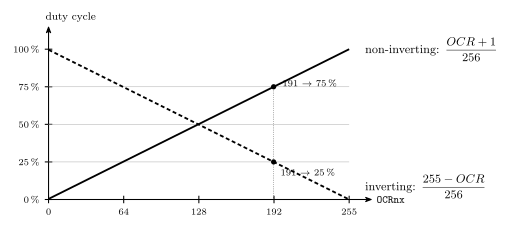
Figure 2: How the compare value maps to duty cycle in mode 3, for the two polarities. In non-inverting mode the pulse runs from the wrap to the match, so it is \(OCR + 1\) ticks of 256 and the duty rises linearly with the register from just under 0.4,% at 0 to 100,% at 255. In inverting mode the pulse runs from the match to the wrap, so it is \(255 - OCR\) ticks: the same line reflected, 100,% at 0 down to 0,% at 255. The two always sum to 100,%. Neither polarity reaches both ends: non-inverting cannot give a true 0,% (a compare value of 0 still gives one tick high) and inverting cannot give 100,%; a program that needs the output fully off disconnects the pin instead.
Setting it up
Four registers, all from the header names (c-preprocessor-and-avr-headers, bit-masking) — timer 0, mode 3, non-inverting on OC0B (PB4), clock ÷ 64, 25 % duty:
DDRB   |= (1<<4);                              /* OC0B is PB4: the timer decides what, DDR decides whether */
TCCR0A  = (1<<COM0B1) | (1<<WGM01) | (1<<WGM00); /* non-inverting on B; fast PWM, TOP = 255 */
TCCR0B  = (1<<CS01) | (1<<CS00);               /* clock / 64: 8 MHz / (256 * 64) = 488 Hz */
OCR0B   = 63;                                  /* (63 + 1) / 256 = 25 % */
After this the CPU never touches the pin; changing the duty cycle is one assignment to OCR0B, and it takes effect at the next wrap. The compare registers are double buffered in the PWM modes: a value written is held back and loaded when the count wraps, so a pulse already under way is never cut short. The frequencies mode 3 can produce at 8 MHz are one per prescaler tap:
| Prescaler | \(f = 8\,\text{MHz} / (256 \cdot N)\) |
|---|---|
| 1 | 31.25 kHz |
| 8 | 3.91 kHz |
| 64 | 488 Hz |
| 256 | 122 Hz |
| 1024 | 30.5 Hz |
For an LED anything from 122 Hz up is flicker-free; for audio the 31.25 kHz setting is the one above hearing. If a frequency between the taps is needed, mode 7 with an OCR0A chosen from the master formula.
Phase correct PWM
The other family of PWM modes has the counter count up and then down — a triangle rather than a sawtooth — and switch the pin at the compare value on both slopes. The pulse is then symmetric about the peak of the triangle, so the centre of every pulse stays at the same point in the period as the width changes, instead of the leading edge staying fixed and only the trailing edge moving. That is smoother for motor control, where the timing of the current pulse relative to the period matters; the cost is a period twice as long for the same top, so half the frequency. Timer 1 adds a phase and frequency correct variant on top. The two families are drawn side by side in 2026-09-17-pulse-width-modulation. This course uses fast PWM only.
See also
- avr-timers-and-counters — the timers: registers, clock select, prescaler, modes, the master formula
- week8-lab-avr-timers — Lab 12:
WGM,CSandCOMbit by bit; the formula worked for a toggling pin - week9-lab-avr-pwm — Lab 13: two LEDs faded on timer 0, and a tone of adjustable pitch and duty cycle on timer 1
- 2026-09-17-pulse-width-modulation — Lecture 16 · 2026-09-14-flow-of-control — Lecture 15
- avr-io-ports — the
DDRbit the timer still needs · timing-diagrams — how the waveforms are drawn