Lecture 15 — Flow of Control
Back to assembly, to fill in the two things a program needs beyond straight-line code: branches and jumps, which is where the AVR’s S flag and the signed/unsigned pairs of branch instructions get explained properly, and procedures, which is where the stack enters. The last part opens the next topic, the AVR’s timer/counters, which Lecture 16 takes up. The evergreen notes are avr-branches-and-jumps, procedures-and-the-stack and avr-timers-and-counters.
Outline
- Flow of control
- Branching
- Procedure Calls
- Use of stacks
- Introduction to AVR Timer/Counters
Background
Three things are assumed from here on: the Atmel AVR CPU (the ALU, general purpose and special purpose registers); the main hardware components of the ATmega324A/ATmega328 microcontroller (AVR CPU, Data Memory, Program Memory, GPIO Ports, Timers/Counters, PWM, Communication Interfaces etc); and AVR assembly language instructions.
The course roadmap has four boxes: AVR Assembly language ⇒ AVR C programming ⇒ ALU Operations ⇒ Interaction with I/O. The course does not walk the row left to right. The control-flow instructions here are a step back into assembly, and the timers at the end are the start of the I/O box.
Flow of control
Flow of control is the sequence that instructions actually get executed in. It is linear (i.e. successive instructions) unless there are branches/jumps, procedure calls, etc.
Plot the program counter against time. Linear flow is a straight rising line: the instructions run one after another, and every fetch-decode-execute (FDE) cycle does PC ← PC + 1. Non-linear flow, the typical case, is the same line broken by jumps: a run, then a drop back (a jump to a lower address) or a rise (a jump forward) at each break. A small program with such breaks:
main:   ...
        ...
        call TEST
PING:   ...
        BREQ ABL
TEST:   ...
        ...
        call PING
ABL:
call TEST jumps down to TEST:. Three labels, two calls and a conditional branch: every kind of non-linearity named below is in those nine lines. Figure 1 draws what the program counter does.
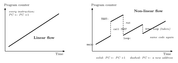
Figure 1: The program counter against time. Left: straight-line code, where every fetch-decode-execute cycle adds one to the PC and the plot is a line of constant slope. Right: the same plot for code with a procedure call, its return and a backward conditional branch. Between the breaks the slope is still one instruction per cycle; each break is a single instruction that loads a new value into the PC instead of the next address. A call jumps forward to the procedure, ret drops back to the instruction after the call, and a taken backward branch drops back to a label above it, which is what a loop looks like. The rises and drops are the only thing that separates the two plots: control flow is the PC being overwritten.
What breaks sequential execution
Most instructions result in the PC being incremented (sequential execution), i.e. PC ← PC + 1, as in the fetch-decode-execute-cycle. Instructions are not executed sequentially when there are:
| ① Branches | conditional |
| ② Jumps | unconditional |
| ③ Procedures | function calls |
| ④ Interrupts / Traps |
The first three are the three sections that follow, in that order. Interrupts are in Lecture 17 (2026-09-21-interrupts; the mechanism is in polling-and-interrupts).
Branches
- AVR branch instructions are typically conditional.
- They are useful in implementing if-else and loops in assembly language.
breqandbrneare the two met so far (2026-09-03-instruction-set-architecture-part-2, and the compare-then-branch figure in avr-program-structure).- For a comparison such as greater than or equal to, the instruction used depends on whether the numbers being compared are unsigned or signed (two’s complement).
breq/brne only ask equal or not, and equality means the same thing for signed and unsigned bytes. Greater than does not: 1111 1111 is 255 unsigned and −1 signed, so whether it is greater than 0000 0001 depends on which you meant, and the machine cannot know. Hence two instructions.
Branches — AVR assembly example
cp r5, r6 computes r5 − r6 and updates the status flags N, Z, C, V and S. Take this pseudo code on two registers:
r5, r6
if (r5 ≥ r6)
    ⋯    (the if part)
else
    ⋯    (the else part)
In the assembly that implements it, the if body goes under the IF: label and the else body goes in the lines directly after the branch:
        cp   r5, r6
        brge IF
        ...              ; the else part
        ...
        jmp  EXIT
IF:     ...              ; the if part
        ...
EXIT:   nop              ; "no operation"
Figure 2 lays the two side by side.
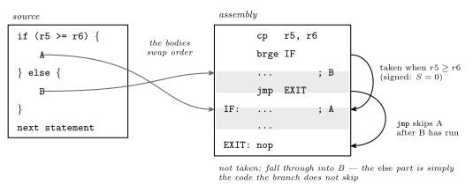
Figure 2: How an if … else becomes assembly. The compare sets the flags; the conditional branch reads them and jumps to the if part when the condition holds. Because a branch can only jump somewhere, the code that runs when the condition fails has to be the code the branch skips over — so the else part sits directly after the branch, ends in an unconditional jmp past the if part, and the if part lives under a label further down. The two bodies end up in the opposite order from the source, which is the thing to expect when reading assembly back into C. EXIT carries a nop only so that the label has an instruction to name; anything that follows the statement would do.
If S = 0, brge makes the jump. There are three cases where it has to, each placed on the signed number line:
| Case | Number line | Flags |
|---|---|---|
① r5 > r6 |
0, r6, r5 in that order, both to the right of zero |
N = 0, V = 0 |
② r5 = r6 |
N = 0, V = 0 | |
③ r5 > r6 |
r6 far to the left, r5 far to the right, and r5 − r6 wrapping round past 127 |
N = 1, V = 1 |
In all three S = N ⊕ V = 0, so brge jumps in all three, which is what greater than or equal requires. Case ③ is the one that justifies the S bit: r5 is a large positive and r6 a large negative, so r5 − r6 is bigger than 127 and overflows into a result whose top bit is 1. The N bit therefore says negative, which is wrong; the V bit says but that sign is an overflow artefact; and their XOR cancels the two to give the true sign. Figure 3 draws the three, and a fourth case, r5 < r6, where the branch must not be taken.
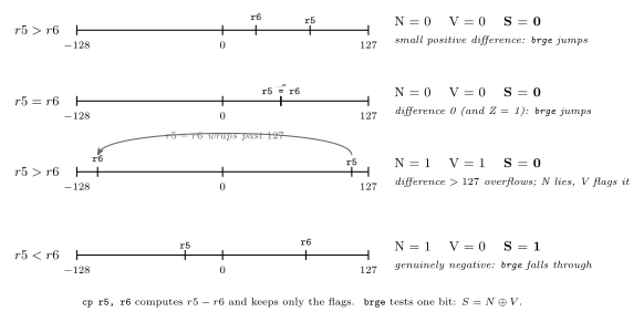
Figure 3: Why a signed comparison tests S and not N. Each panel is the signed number line of an 8-bit register, \(-128\) to \(127\), with the two operands of cp r5, r6 marked and the flags the subtraction sets. In the top three cases \(r5 \ge r6\) and brge must jump; in the first two the difference fits and N alone would do. In the third the true difference is larger than 127, the 8-bit result wraps to a negative pattern, and N reports the wrong sign — but the overflow flag V is set at the same time, and S = N \oplus V corrects it back to 0. The bottom panel is the case the branch must not take: \(r5 < r6\) gives a genuinely negative difference, N = 1 with V = 0, so S = 1. Reading S gives the right answer in all four; reading N fails in the third.
AVR “S” status bit
Two status bits met earlier:
- N bit = negative (1 if the sign bit of the result is 1)
- V bit = two’s complement overflow
The AVR also has the S bit: S = N ⊕ V, the sign bit corrected for overflow. If overflow happens, the sign bit will be wrong, so instead of checking the N bit, check the S bit.
S has been in the status register since Lecture 10 (avr-architecture); this is what it is for. It exists so that a signed less than is one flag test rather than two.
Branch instructions
Each conditional branch tests one status bit for one value:
| Branch if status bit is equal to | C | N | V | S = N⊕V | Z |
|---|---|---|---|---|---|
| 0 | brsh (= brcc) |
brpl |
brvc |
brge |
brne |
| 1 | brlo (= brcs) |
brmi |
brvs |
brlt |
breq |
Ten instructions, one per flag per value. Two of the columns are the comparisons that matter here:
| unsigned | brsh — same or higher |
brlo — or lower |
| signed | brge — greater than or equal |
brlt — lower than |
A worked example: r5 = 1111 1111, r6 = 0000 0001. Read as unsigned, cp computes 255 − 1, which is positive, so brsh is the branch taken. Read as signed, cp computes −1 − 1, which is negative, so brlt is the branch taken. Same two registers, same cp, same flags — and one branch says r5 is higher, the other says r5 is less. Both are right. The unsigned pair reads C, because an unsigned subtraction that needs a borrow is exactly one whose result went below zero; the signed pair reads S, for the reason worked through above. The programmer chooses the instruction and thereby declares what the bits meant, the same decision as lsr versus asr in 2026-09-03-instruction-set-architecture-part-2. Full table and the loop idioms in avr-branches-and-jumps.
Jumps
The AVR has three jump instructions:
jmp label — absolute jump, 32-bit instruction, 3 cycles |
label is a 14-bit address |
rjmp label — relative jump, 16-bit instruction, 2 cycles |
label becomes an offset, − or + up to 2048 cells |
ijmp — indirect jump, 16-bit instruction, 2 cycles, jump target is given in Z register |
Why two sizes. jmp carries the destination as a full program-memory address, and an address into the ATmega324A’s 16 K-word flash needs 14 bits — more than fits in a 16-bit instruction word alongside the opcode, so jmp takes two words (avr-instructions on instruction encoding). rjmp instead carries a signed offset from the current PC, 12 bits of it, so it can reach ±2 K words — 2048 cells either way — in a single word and one cycle less. Almost every jump in a small program is within that range, which is why the labs’ template uses rjmp for its main loop. ijmp takes the address from Z, the pointer register of addressing-modes: the destination is a value, computed at run time, rather than a label fixed at assembly time.
Procedures
A procedure is a group of instructions that performs some task.
- It may have operands (arguments or parameters).
- It may produce result(s).
- It can be invoked (called) from multiple places in a program, even from within itself: a recursive procedure.
- After invocation, control returns to the statement after the call.
- Good use of procedures helps structure a program well.
- Other names: subroutine, function (C, Python), method (Java).
The shape of a call:
main:   ...
        ...
        call TEST      ; args ?
        [xxx]          ; the instruction after the call

TEST:   ...
        ...
        ret            ; returns results ?
call TEST jumps down to TEST:, and ret jumps back up to [xxx], the instruction after the call. The two questions in the comments are among the procedure issues below.
Call instructions
The AVR has three call instructions:
call label |
direct subroutine call, 4 cycles, 32-bit instruction |
rcall label |
relative subroutine call, 3 cycles, 16-bit instruction |
icall |
indirect call, 3 cycles, 16-bit instruction |
The same three flavours as the jumps — absolute, relative, indirect — each one cycle longer than its jump, which is the cost of saving the return address.
Procedure issues
Procedures raise three questions:
- After a procedure finishes, control returns to the statement after the call. How does the procedure know where to return to?
- How are operands specified (i.e. arguments passed)?
- How is the result returned?
The first takes the most answering. The other two are answered together, briefly, once the stack is in place.
Return address
There are three places the return address could be stored:
| Option | Problem |
|---|---|
| A single fixed memory address or register for all procedure calls | procedures can’t call other procedures |
| A memory location per procedure | doesn’t allow for recursion |
| A stack |
The second option fails for a procedure that calls itself:
main:   ...
        call TEST
        [xxx]
TEST:   ...
        call TEST
Two calls of TEST are live at once, so two return addresses must be kept at once; one slot per procedure holds one. Two return addresses kept one above the other are already a stack.
Each option fails on the next level of nesting. A single slot works until a procedure calls a procedure — the second call overwrites the first’s return address and main is never returned to. A slot per procedure works until a procedure calls itself. A stack works for any depth, because every call pushes and every ret pops, so the return address that comes off is always the one that went on most recently, which is the innermost call still running. Figure 4 draws the mechanism.
Procedure call — use of stack
call pushes onto the stack and ret pops from it:
main:   ...
        ...
     →  [xxx]  call TEST     ─── push ──→   the stack
TEST:   ...
        ...
        ret               ←── pop  ───
The stack is a region of data memory, at the opposite end from the data that memory already holds. The pushed cell is xxx, with SP pointing at it, and each cell is 8 bits wide. A stack frame stacks three things together: xxx / args / results.
The stack pointer is the register that keeps track of the top of the stack. On the AVR it is SPH:SPL, two I/O registers for a 16-bit stack pointer.
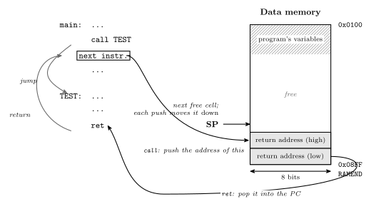
Figure 4: What call and ret do with the stack. The stack is a region at the top of data memory, addressed downward: it starts at RAMEND and grows toward lower addresses as things are pushed, so it approaches the program’s variables from above. call TEST pushes the address of the instruction after itself — the return address — and moves the stack pointer down; ret pops that address back into the PC and moves the pointer up. On the AVR each cell is one byte and the PC is wider than a byte, so a return address occupies two cells and SP moves by two. The pointer itself lives in two I/O registers, SPH:SPL, and must be set to RAMEND before the first call, or the first push lands wherever the reset value happens to point.
Why the stack is at the top. Data memory’s SRAM runs from 0x0100 to 0x08FF (memory-models); the program’s variables are allocated from the bottom of that region upward, so the stack is started at the very top, RAMEND, and grows down toward them. The two can grow toward each other for as long as the memory lasts, and neither needs to know in advance how much the other will use.
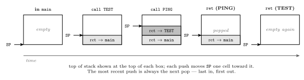
Figure 5: The stack through a nested call. Five snapshots of the stack region, one per event, for main calling TEST and TEST calling PING. Each call pushes one return address on top of whatever is there; each ret pops the top one, which is always the return address of the call made most recently and not yet returned from. After the inner ret the outer return address is exactly where the outer call left it, so TEST returns to main correctly even though another call happened in between. A single fixed slot would have been overwritten by the second push; this is the property that a per-procedure slot lacks for recursion and a stack has for any depth.
Assembly programs — stack initialisation
Assembly language programs must initialise the stack before using it:
.def temp=r16
    ldi temp,low(RAMEND)
    out SPL, temp
    ldi temp,high(RAMEND)
    out SPH, temp
Four instructions that go at the top of RESET: in every program that will ever call anything. RAMEND is the assembler’s name for the last SRAM address, 0x08FF on the 324A; low() and high() split it into its two bytes because SPL and SPH are two 8-bit I/O registers and there is no 16-bit out. This is the line the Lab 10 template was missing (avr-program-structure) — it did not need one, because nothing in it called a procedure. In C the compiler emits this for you; that is one of the things main costs.
Procedure call — arguments and results
There are two ways to pass arguments to a procedure and to return results from it:
- use registers
- or use the stack
Registers are the fast answer for a few small values — put the argument in r24, say, and the procedure reads it from there — and the AVR C compiler does exactly that for the first few arguments of a function. The stack is the general answer: the caller pushes arguments before the call, the procedure finds them just above the return address, and results can go back the same way. That is the stack frame — xxx / args / results stacked together. Conventions for which registers and in what order are in procedures-and-the-stack.
AVR timers/counters
The ATmega324A has three timer/counter blocks on its block diagram: 8-bit T/C 0, 16-bit T/C 1 and 8-bit T/C 2. The diagram also has a fourth, 16-bit T/C 3, but that one is on the larger family members, not the 324A (avr-architecture). On the pinout, six pin functions belong to the timers: OC0A and OC0B on PB3 and PB4, OC1B and OC1A on PD4 and PD5, OC2B and OC2A on PD6 and PD7. These are the output compare pins, one pair per timer, and they are where a timer reaches the outside world; Lecture 16 uses them.
- A counter is a binary up/down counter clocked on some event.
- A timer is a counter clocked by a regular clock.
So the hardware is one thing — a counter of the kind built in counters, now wide and in silicon — and timer versus counter is only a statement about where its clock comes from. Clock it from a pin and it counts events; clock it from the system clock and, since every tick is the same length, its count is elapsed time.
ATmega324A — timer/counter clock sources
The three timer/counters:
| Width | Clock sources | |
|---|---|---|
| 0 | 8 bit (0 to 255) | STOPPED, CLK, CLK/8, CLK/64, CLK/256, CLK/1024, external pin rising edge, external pin falling edge — CLK = system clock |
| 1 | 16 bit (0 to 65535) | the same list |
| 2 | 8 bit (0 to 255) | STOPPED, CLK, CLK/8, CLK/32, CLK/64, CLK/128, CLK/256, CLK/1024 — CLK = system clock or external oscillator |
CLK is 8 MHz, the system clock the lab boards run at. Timer 2 trades the two external-pin inputs for two extra divisors and can run from a separate crystal on the TOSC1/TOSC2 pins, the port-C pins that avr-io-ports noted were broken out separately on the block diagram; that is what makes it the real-time-clock timer.
Clock prescaling
Take four clocks: CLK, CLK/2, CLK/4 and CLK/8. The counter advances on the rising edges, and over the same stretch of time there are four on CLK, two on CLK/2, and one each on /4 and /8. An 8-bit count climbs a staircase from 0 to 255, and an event happens when the count reaches the top. The staircase is steepest for CLK and shallower for each further division. Drawn as a sawtooth, the count has short ramps of period T for CLK, and long ramps spanning eight clock periods for CLK/8.
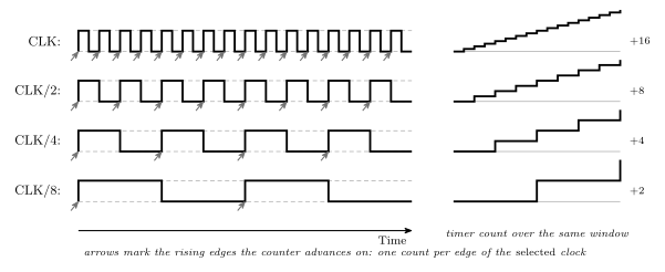
Figure 6: What a prescaler does to a timer. The counter advances by one on every rising edge of its selected clock; dividing the system clock by \(N\) stretches every count to \(N\) system-clock periods. The staircase under each track is the resulting count against the same time axis: at CLK the timer climbs eight steps in the window shown, at CLK/8 it climbs one. A full sweep from 0 to 255 therefore takes \(256 \cdot N\) system-clock cycles, and the prescaler is the coarse control over how long a timer’s period is, before the compare registers give fine control. At 8 MHz the sweep is 32 µs with no prescaling and about 33 ms at CLK/1024.
The prescaler is a chain of flip-flop dividers (counters — a ripple counter’s stages are exactly CLK/2, CLK/4, CLK/8, …), and the timer is handed one tap of it. The staircases are the point: the same 0-to-255 sweep takes eight times as long on CLK/8 as on CLK, and 1024 times as long on CLK/1024. At 8 MHz that is the difference between 32 µs and 33 ms per sweep, which is the range that makes an 8-bit counter useful for both microsecond and human-scale timing.
Clock selection
The clock source for timer/counters 0 and 1 is chosen by a multiplexer with seven inputs: 0 (clock stopped), CLK, CLK/8, CLK/64, CLK/256, CLK/1024, and the external source, which enters twice, once directly and once through an inverter so that either edge can be chosen. Three select lines pick the input; the output is the counter clock source.
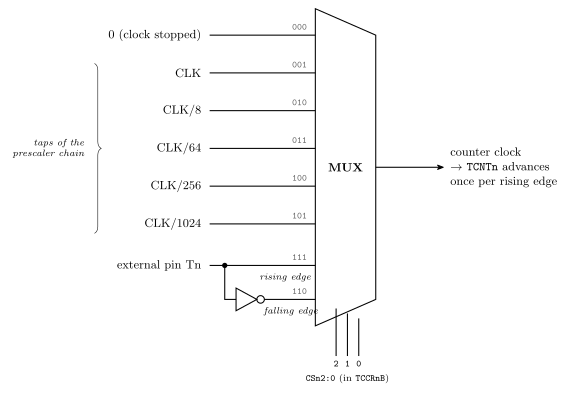
Figure 7: The clock selection multiplexer in front of each timer/counter. Eight inputs, three select bits: the CSn2:0 field of the timer’s control register picks one, and a code of 000 selects a constant 0, which is how a timer is stopped without any separate enable. Five of the inputs are taps of the prescaler chain. The external pin Tn enters twice, plain and inverted, so that the counter can advance on whichever edge the application wants; choosing one of those two codes is what turns the timer into an event counter. The select codes are the ones the control register uses for timers 0 and 1; timer 2 has the same shape with the two external inputs replaced by extra prescaler taps.
Choosing an input is one three-bit field in a control register, CS02:0 for timer 0 and CS12:0 for timer 1; the codes are in the figure and in avr-timers-and-counters, and Lab 12 sets them from C. What happens when the timer counts — output compare, the modes, and PWM — is Lecture 16, 2026-09-17-pulse-width-modulation.
See also
- avr-branches-and-jumps — the ten conditional branches, signed versus unsigned,
jmp/rjmp/ijmp, and theif/loop idioms - procedures-and-the-stack —
call/ret, the return address,SPH:SPL,RAMEND,push/pop, passing arguments - avr-timers-and-counters — the three timer/counters, their registers, clock sources and modes
- avr-architecture — the status register, and
S = N ⊕ V - avr-program-structure — labels, the template, and compare-then-branch
- avr-instructions · addressing-modes · memory-models · counters · fetch-decode-execute-cycle
- 2026-09-03-instruction-set-architecture-part-2 — Lecture 12, where
breq/brnewere introduced - 2026-09-17-pulse-width-modulation — Lecture 16 · week8-lab-avr-c-programming — Lab 11 · week8-lab-avr-timers — Lab 12