Lecture 17 — Interrupts
The last of the four ways the program counter leaves its sequence. The list is branches, jumps, procedures, interrupts/traps, and the first three are in Lecture 15 (2026-09-14-flow-of-control). An interrupt is a call that nobody wrote: a device signals the CPU, and the hardware diverts the running program into a handler and later puts it back exactly where it was. The stack comes first, because that is where exactly where it was is kept. Then comes the problem the CPU has with slow I/O and the two ways to solve it, polling and interrupts, followed by the three issues an interrupt raises: finding the handler, preserving the registers, and what to do when a second interrupt arrives. Each issue gets the AVR’s answer, in assembly and in C. Traps, the software counterpart, come last. The evergreen notes are polling-and-interrupts (the mechanism, on any CPU) and avr-interrupts (the ATmega324A’s vector table, the ISR template, ISR() in C, and setting an interrupt up); the stack itself is procedures-and-the-stack.
The fast CPU and slow I/O
The topic is input/output: the stack revisited, then polling, then interrupts. The stack is what the rest is built on.
The problem is the interface between a fast CPU and slow I/O:
\[\text{CPU (FAST)} \;\longleftrightarrow\; \text{I/O (SLOW)}\]
On the ATmega324A block diagram (avr-architecture), the CPU side is the AVR CPU, running at 8 MHz, with FLASH and SRAM. The I/O side is PORT A, PORT B, PORT C, the A/D converter, and the three timer/counters 8bit T/C 0, 16bit T/C 1 and 8bit T/C 2.
Everything on the I/O side runs at the pace of the outside world. A pin changes when someone presses a button, a timer matches when its count gets there, a converter finishes when the conversion is done. Meanwhile the CPU is completing an instruction every one or two cycles of an 8 MHz clock. For scale, a button held down for a tenth of a second spans 800 000 of those cycles. The question is how the fast side finds out when the slow side has something for it.
AVR Stack
Two instructions move one register on and off the stack:
push Rrplaces the value in registerRron top of the stack, then adjusts the stack pointer: SP ← SP − 1.pop Rdplaces the value on top of the stack in registerRd, and adjusts the stack pointer: SP ← SP + 1.
The procedure-call instructions are call, rcall, icall and ret. For example, call label does three things:
- it places the program counter value (the return address) on top of the stack;
- SP ← SP − 2, since 16 bits are needed for the return address;
- PC ← the value of
label.
The stack is in data memory and grows towards address 0x000. Say the stack already holds some earlier values and Rr holds 100. push Rr writes 100 into the cell SP points at, the empty cell just above the earlier values, and leaves the stack pointer one cell further up, at SP − 1. pop Rd moves the stack pointer back down and takes the 100 out into Rd.
This is the summary of procedures-and-the-stack, and one detail matters for everything that follows: SP points at the next free cell, so a push writes first and then decrements, and a pop increments first and then reads. A call lowers SP by 2 because the stack is 8 bits wide and a return address is not, so a call uses two cells.
Function call — example
In program memory, main: has a few instructions and then call TEST. The instruction after the call is at address 100. Further down is TEST:, whose instructions end in ret. The call and the return take five steps:
- PC ← 100
- push PC, which puts the 100 on the stack
- PC ← TEST, and
TESTruns - pop PC, at the
ret - the instruction at address 100 runs
Step 1 is the return address: 100 is the address of the instruction after the call, which is where the PC would have gone next anyway. The call saves it, overwrites the PC with the target, and ret puts the saved value back.
Program memory has 2¹⁴ cells, so an address is 14 bits. The stack is in data memory, where a cell is 8 bits wide. The address does not fit in one cell, so the 100 takes the two cells above the earlier values and the stack pointer is left at SP − 2:
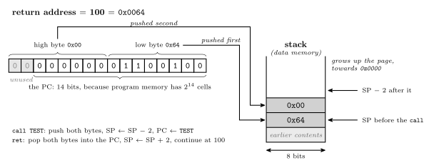
Figure 1: Why a call moves the stack pointer by two. Program memory on the ATmega324A has \(2^{14}\) cells, so the program counter is 14 bits wide, and the return address it holds (here 100, the address of the instruction after the call) does not fit in one byte. The stack is data memory, 8 bits to a cell, so the address is padded to 16 bits and stored as two bytes: the low byte goes into the free cell the stack pointer marks, the high byte into the one above it, and the stack pointer ends two cells further up, at SP − 2. ret reads the same two cells back into the PC and moves SP down by two. A push or pop of a register moves one byte and changes SP by one; mixing the two up is how a procedure that pushes without popping ends up returning to a register’s contents.
Worked: what is in r17 and r18?
What values are in r17 and r18 after this code?
ldi  r17, 20
ldi  r18, 33
push r17
push r18
pop  r17
clr  r17
pop r17| r17 | r18 | |
|---|---|---|
| A. | 0 | 20 |
| B. | 0 | 33 |
| C. | 20 | 20 |
| D. | 20 | 33 |
| E. | 33 | 20 |
| F. | 33 | 33 |
Answer: D. Take the instructions in the order they run and keep a running record of the two registers. r17 = 20 after its ldi, then 33 after the first pop, then 0 after the clr, then 20 after the second pop. r18 = 33 throughout. After the two pushes the stack holds 20 with 33 on top of it. The first pop takes the 33 back off and the second takes the 20.
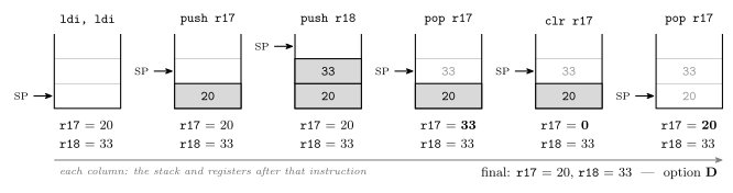
Figure 2: The seven instructions, with the stack drawn after each one (the two ldis share the first column). The stack pointer always marks the next free cell, and the stack grows up the page. The question turns on pop taking whatever is on top, with no record of which register put it there: the first pop r17 receives the 33 that r18 pushed, clr zeroes r17, and the second pop r17 receives the 20 that r17 pushed originally, so the clr has no lasting effect. r18 is never written after its ldi. A popped value is not erased; it stays in memory (grey) but sits above the stack pointer, so the next push will overwrite it.
The trap is reading pop r17 as give r17 back its value. The stack keeps values, not names: pushes and pops are matched by order, not by register, which is also what makes the stack useful for swapping two registers or handing a value from one to another. The two pushes and two pops balance, so the stack pointer ends where it began. That matters for interrupts, because an ISR that leaves the stack unbalanced returns to the wrong place.
CPU Interacting with I/O
The CPU operates at a faster speed than I/O, and I/O can sometimes be asynchronous. The CPU needs to know:
- when data is available from input devices;
- when output devices are ready to accept data.
There are two options: polling-driven I/O and interrupt-driven I/O.
Asynchronous is the harder half: I/O is not just slow, it is unrelated to the CPU’s clock and to where the program is, so a key can be pressed during any instruction. The two options are drawn side by side against the same events in polling-and-interrupts.
Polling the Input(s)
In polling, the processor periodically asks devices and waits for responses. This is inefficient, because time is wasted asking and waiting, but it may be OK if the processor has nothing else to do.
Polling is what every lab program so far has done: read PINA each time round the main loop, or spin on TIFR1 until the timer flag is set (avr-timers-and-counters). It costs in two places: every ask that finds nothing, and the delay between an event and the next ask. When the processor has nothing else to do, neither cost matters.
Interrupts
With interrupts, the device tells the CPU when it is ready. This is more efficient for the CPU, and it changes the flow of control. Examples:
- a device is ready to accept more output: the serial transmit buffer is empty;
- a device has input ready: a key is pressed on the keyboard;
- a regular interrupt: a timer generates an interrupt every e.g. 20 ms.
An interrupt arrives while some instruction of main is running. Each source of interrupt has its own routine, such as ISR0: and ISR_timer:, sitting in program memory below main like any procedure, and each ends in reti rather than ret.
The three examples are the three kinds of source that the AVR vector table below groups: output ready (a USART’s data register empty), input ready (an external interrupt pin), and time (a timer’s compare match or overflow). The change in the flow of control is the link back to Lecture 15. The PC leaves its sequence, as it does for a branch, jump or call, but here no instruction in the running program asks it to.
Interrupts — the handler, and three issues
When the CPU receives an interrupt, it executes software to handle the interrupt. The software routine is called an interrupt handler or interrupt service routine (ISR). When the handler completes, control must be returned to where the program left off. That raises three issues:
- How does the CPU know where the ISR is?
- All registers, including the status register, must have their values preserved. How?
- What happens if another interrupt arrives while an interrupt is being serviced?
Issue 1 is answered by the vector table, issue 2 by transparency and the ISR template, and issue 3 by nesting and priority.
Finding the Interrupt Handler
This is issue 1. The CPU determines the address of the ISR from the interrupt source, then jumps to that address. It finds the address by looking in the interrupt vector table, which is often at the beginning of memory. The table is either a table of addresses or a table of jump instructions. The AVR uses a table of jump instructions.
Vector sometimes refers to the interrupt number (the index into the vector table) and sometimes to the address of the interrupt handler itself.
The two kinds of table differ in who does the last step. With a table of addresses, the CPU reads the entry for the source and loads the number it finds into the PC. With a table of jumps, the CPU loads the PC with the address of the entry itself, and the instruction stored there — a jmp — does the rest. The AVR does the second. That is why each AVR entry is a two-word jmp (avr-branches-and-jumps) and why consecutive entries are two addresses apart.
The two meanings of vector are worth keeping in mind when reading the datasheet and avr-libc. The vector number is the entry’s row in the table (INT0 is vector 2), and the vector address is where that row sits in program memory (0x0002). In C, the vector’s name (INT0_vect) identifies the entry. avr-libc numbers the entries from 0, with RESET as 0, so the same entry is its vector 1: one more reason to check which counting is meant.
Finding the Interrupt Handler — the whole path
Take a timer interrupt that arrives while an instruction of main is running. Call the return address xxx. Below main in program memory are the handlers, ISR_timer: and ISR0:, each ending in reti. The vector table is at the very top of program memory:
| Entry | Address |
|---|---|
jmp ISR0 |
0x0000 |
jmp ISR1 |
0x0002 |
| ⋮ | |
jmp ISR_timer |
0x0014 |
The hardware pushes the return address xxx onto the stack (push PC) exactly as a call would, loads the PC with the table address for the source (0x0014), and the jmp stored there reaches ISR_timer. The handler’s reti then pops the return address back into the PC (pop PC), and main carries on. The numbering of the first two entries is generic: on the ATmega324A, 0x0000 is RESET and 0x0002 is INT0. The third is exact. 0x0014 is vector 11, Timer/Counter2 Compare Match B, so ISR_timer is the right name for what sits there. The path is drawn step by step, with the stack, in avr-interrupts.
AVR Interrupts
The vector table of the ATmega324A (datasheet, pages 69-70). The last column sorts the sources into kinds of I/O:
| Vector | Program Addr | Source | Interrupt Definition | Kind |
|---|---|---|---|---|
| 1 | 0x0000 | RESET | RESET, Watchdog Reset, etc. | |
| 2 | 0x0002 | INT0 | External Interrupt Request 0 | GPIO |
| 3 | 0x0004 | INT1 | External Interrupt Request 1 | GPIO |
| … | ||||
| 11 | 0x0014 | TIMER2_COMPB | Timer/Counter2 Compare Match B | T/C |
| 12 | 0x0016 | TIMER2_OVF | Timer/Counter2 Overflow | T/C |
| … | ||||
| 20 | 0x0026 | SPI_STC | SPI Serial Transfer Complete | Comms |
| 21 | 0x0028 | USART0_RX | USART0 Receive Complete | Comms |
| 22 | 0x002A | USART0_UDRE | USART0 Data Register Empty | Comms |
| 23 | 0x002C | USART0_TX | USART0 Transmit Complete | Comms |
| 24 | 0x002E | ANALOG_COMP | Analog Comparator | |
| … |
Three things can be read straight off it:
- Address = 2 × (vector − 1). Entries are two program-memory words apart because each holds a two-word
jmp. - RESET is vector 1. Reset is handled as the first entry of the same table, which is why every program begins with
jmp RESETat0x0000(avr-program-structure). - The three groups are kinds of I/O. GPIO: pins that raise an interrupt on an edge or level. T/C: the timers. Comms: the serial interfaces. The first two are the ports and timers on the I/O side of the block diagram.
All 31 rows, with their C names, are listed in avr-interrupts.
Preserving Register Values
This is issue 2. If an ISR uses registers, it must save copies of those registers before using them and restore the values afterwards, before returning from the interrupt. In particular, the status register must be saved. Many CPUs do this automatically. The AVR does not: it must be done manually, if the status register would be changed by the handler. This is called transparency: when the ISR finishes, the computer is in the same state as it was before the interrupt.
A procedure’s caller knows the call is coming and can agree with the procedure which registers it may use (procedures-and-the-stack). The code an interrupt lands in has no such chance: the interrupt can arrive between any two instructions. That includes the gap between a cp and the breq that reads its result. If the ISR changes Z and does not put it back, the branch goes the wrong way. It does so only when the interrupt happens to land in that two-instruction window, which is what makes the bug so hard to find. So everything the ISR touches must be restored, the status register above all, and the ISR is then transparent: the interrupted program cannot tell it ran.
Interrupt Summary — Sequence of Actions
The whole sequence is fourteen steps, shared between the hardware and the ISR. Hardware:
- Device asserts interrupt line
- CPU determines source of interrupt
- Push PC (return address) onto stack
- Some CPUs push the status register as well, but not the AVR
- Determine address of ISR (e.g. from the interrupt vector table)
- CPU puts address of ISR into PC
- CPU disables interrupts
Software (ISR):
- Save all registers to be used
- Determine source of interrupt (if this is not done by hardware)
- Handle the interrupt by executing the ISR code (e.g. do the required input or output)
- Restore registers
- Execute return from interrupt instruction
Back to hardware:
- Interrupts are re-enabled
- CPU pops PC off the stack and restores it
- Execution continues from where it was “interrupted”
Steps 6 and 12 are a pair. On the AVR, disables interrupts is the hardware clearing the I bit of the status register (avr-architecture) as it takes the vector, and re-enabled is reti setting it again. Between them, no other interrupt can start. Step 8 mostly does not arise on the AVR, because every source has its own vector and so the hardware has already told the ISR which source fired. The exception is the pin-change interrupts: PCINT0–PCINT3 each cover a whole port, and their handler must work out which pin changed. Steps 11 to 13 are a single instruction: reti is ret plus set I. The whole sequence is drawn, with the stack and the I bit at each stage, in polling-and-interrupts.
Instructions which change the Status Register
The Instruction Set Reference says which instructions change the status register. Its Flags affected column is summarised for the instructions this course uses in avr-instructions. The short version is enough to decide whether an ISR must save SREG:
| Change flags | Change no flags |
|---|---|
arithmetic: add, adc, sub, subi, inc, dec, neg |
data movement: ldi, mov, lds, sts |
logic: and, andi, or, ori, eor, com, clr, tst |
I/O: in, out, sbi, cbi |
compare: cp, cpi |
stack: push, pop |
shifts and rotates: lsl, lsr, asr, rol, ror |
jumps, calls, returns and branches |
An ISR built only from the right-hand column cannot disturb the flags, so it has no need to save them. The worked question after the ISR template tests that rule. (Three instructions change the I bit and nothing else: sei, cli and reti.)
Template AVR ISR
isr_label:                ; Save any registers used
            push r0
            in   r0, SREG
            push r0

            ; … perform operation
            ; … (usually Input/output)

            ; Restore registers
            pop  r0
            out  SREG, r0
            pop  r0
            ; return from interrupt
            reti
The first three instructions store on the stack: r0, then the SREG copy that in r0, SREG takes and the second push r0 saves. The three before the reti restore from the stack: out SREG, r0 puts the flags back and the last pop r0 puts r0 back.
Each line is there for a reason:
r0is pushed first becauseSREGcannot be pushed directly.pushtakes a general-purpose register, andSREGis an I/O register, so its value has to travel through one. That register’s own contents must be saved before it is used as the carrier.- The flags saved are the interrupted program’s. Apart from I, which the next point covers, nothing between the interrupt and
in r0, SREGchanges them, sincepushdoes not touch the flags. They are exactly what the interrupted code last left inSREG. - The restore is the mirror image, because the stack returns things in reverse order. The saved
SREGcopy comes off first, so it is popped intor0and written toSREG; thenr0’s own value comes off. - The saved I bit is 0. The hardware cleared I before the first instruction of the ISR ran, so the copy taken by
in r0, SREGhas I = 0, and writing it back leaves interrupts off. It isreti, the last instruction, that turns them on again.
Any other register the body uses gets its own push after these three and its pop before the restore, in reverse order. The stack through the whole template is drawn in avr-interrupts.
Worked: a suitable ISR for port B to port C
Which of these is a suitable interrupt service routine that reads a byte from the port B pins and outputs it to port C? There are four handlers for INT0, each with .def temp = r16:
; (a)
int0: push temp
      in   temp, SREG
      push temp
      in   temp, PINB
      out  PORTC, temp
      reti
; (b)
int0: push temp
in temp, SREG
push temp
in temp, PINB
out PORTC, temp
pop temp
pop temp
out SREG, temp
reti; (c)
int0: push temp
in temp, SREG
push temp
in temp, PORTB
out PINC, temp
pop temp
out SREG, temp
pop temp
reti; (d)
int0: push temp
in temp, PINB
out PORTC, temp
pop temp
reti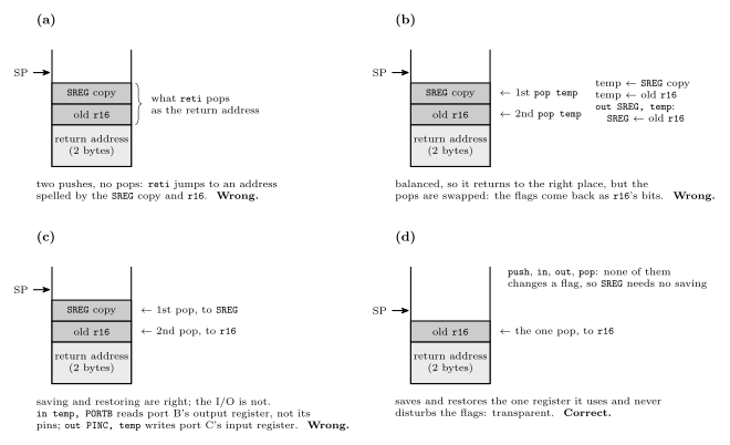
Figure 3: The four candidate handlers, each with its stack drawn at its fullest, just before it starts to unwind. (a) pushes two bytes and pops none, so reti takes the saved SREG copy and r16 as its return address and jumps into the program at an address made of them. (b) pops the two bytes in the wrong order: the stack is balanced, so it returns correctly, but SREG receives r16’s old value and the interrupted code resumes with meaningless flags. (c) saves and restores exactly as the template does, but reads PORTB, port B’s output register, instead of PINB, its pins, and writes to PINC, port C’s input register, instead of PORTC; on this chip a 1 written to a PINx bit toggles the matching PORTx bit, so the outputs would flip rather than copy port B. (d) saves the one register it uses and never touches the flags, since in, out, push and pop change none of them; it is correct, and the shortest.
The answer is (d). It looks the least careful of the four because it skips the SREG lines, but SREG has to be saved only if the status register would be changed by the handler, and nothing in (d) changes it. The other three each make a different mistake worth recognising. (a) leaves the stack unbalanced, (b) restores in the wrong order, and (c) confuses a port’s three registers (avr-io-ports). PINx is what the pins read, PORTx is what the port drives, and the two are not interchangeable. All four assume, as the question does, that port B’s pins were set as inputs and port C’s as outputs during initialisation.
AVR Interrupts in C
Start with #include <avr/interrupt.h>. An interrupt handler can then be written as a C function, using the special ISR macro:
ISR(INT0_vect) {
    … /* code here */
}
This is the handler for the INT0 external interrupt. The interrupt vector table setup and the register saving and restoring happen automatically. The name to use is the source name from the datasheet followed by _vect. The AVR LibC manual documents avr/interrupt.h.
The argument, INT0_vect, is the name that matters. ISR is not a function name but a macro, and what it is given is the vector. From that the compiler does the three things the assembly programmer does by hand: it places a jump to this function in the vector table at INT0’s entry (0x0002), wraps the body in the save-and-restore the template writes out, SREG included, and ends it with reti instead of ret. The naming rule is the Source column of the table plus _vect, which gives TIMER2_COMPB_vect, USART0_RX_vect, ANALOG_COMP_vect, and so on.
Setting up interrupts
Besides the handler, the program also needs to:
- set up the conditions for the interrupt;
- enable that particular interrupt. An I/O register bit for each interrupt controls whether that interrupt is enabled or not;
- clear the specific interrupt flag, to ensure the interrupt doesn’t trigger immediately. This is usually done by writing 1 to some I/O register bit;
- turn on interrupts globally, with the
sei()macro (the same as theseiassembly language instruction).
These are four switches, and an interrupt reaches its handler only when all of them are on. For a timer 1 compare-match interrupt:
| Step | Timer 1, compare A |
|---|---|
| conditions | TCCR1A/TCCR1B and OCR1A: the mode, prescaler and match value (avr-timers-and-counters) |
| enable that interrupt | OCIE1A in TIMSK1 |
| clear its flag | TIFR1 = (1<<OCF1A);, a 1 written to clear it |
| enable globally | sei();, which sets I in SREG |
Clearing the flag first matters because the flag is set by the hardware whether or not its interrupt is enabled. A timer that has been counting while the interrupt was off has very likely matched already. Without the clear, the moment the enable and sei() go on, the CPU would take a stale interrupt for an event that happened long before. The complete program is in avr-interrupts.
Volatile variables in C
A variable that can be changed outside the normal flow of a program (e.g. in an interrupt handler) should be declared as volatile:
volatile uint8_t count;This prevents the code optimiser from assuming the variable’s value doesn’t change and optimising code away.
For example, take a loop in main:
int i = 0;
while (i < 10) {
    …
}
and a handler that writes the variable:
ISR() {
    i = 100;
}
The optimiser concludes that the condition i < 10 is always TRUE.
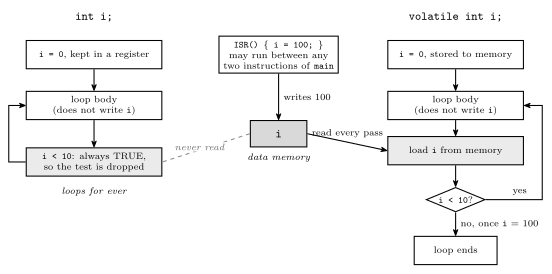
Figure 4: What volatile changes. main loops while i < 10, nothing in the loop body writes i, and an ISR sets i = 100. The compiler analyses main on its own and has no way to know that a handler may run between any two of its instructions. Without volatile it may keep i in a register, or conclude that i < 10 can never become false and drop the test entirely: the ISR’s write reaches memory, but the loop never reads memory again and never ends. With volatile, every read of i in the source becomes a load from memory in the machine code, so the first test after the ISR has run sees 100 and the loop exits. The program is identical in both columns; only what the compiler is permitted to assume differs.
The compiler is not wrong to optimise; it is working from a program that, as far as it can see, never changes i in the loop. volatile is how the programmer tells it about the other writer. The declaration of count uses uint8_t where the loop uses int, and uint8_t is the safer choice on this CPU, for a reason drawn out in avr-interrupts. A one-byte variable is read by a single instruction, so an interrupt cannot land halfway through reading it.
Nested Interrupts
This is issue 3. There is a chance that another device interrupts during ISR execution. There are two policies:
- Simply disable subsequent interrupts during the ISR. Usually, the global interrupt enable flag is one of the flags restored by the return from interrupt instruction.
- Better, prioritise interrupts, and allow higher priority interrupts to interrupt lower priority ones (and not vice versa, or at the same level). Many CPUs support this, but not the AVR.
The first is the AVR’s: interrupts are off for the whole ISR. On a CPU that saves the status register automatically, restoring it on return brings the enable flag back with everything else. The AVR does not save SREG, but reti sets I directly, which comes to the same thing. The second policy — priority nesting, where only a more urgent source may interrupt an ISR — is the better one, and the AVR does not have it. The three policies, including the one the AVR allows by choice, are compared in polling-and-interrupts.
AVR Interrupt Priority
Priority is determined by vector: the lowest vector is the highest priority. The top of the vector table is HIGH priority and the bottom is LOW. So RESET outranks everything, INT0 is the highest-priority real interrupt, and down the table external pins come before timers, which come before the serial interfaces.
Three rules say when priority applies:
- Priorities only matter when two (or more) interrupts are waiting to be serviced. The highest priority (lowest vector) is serviced first.
- Interrupts are disabled during an ISR, and re-enabled by the
retiinstruction. - It is possible to enable interrupts during an ISR. Priorities are not relevant then: any incoming (or pending) interrupt may be serviced, even if it is lower priority.
The first rule is the one people get wrong. On the AVR, priority does not mean that a more important interrupt can cut into a less important ISR. It only decides the order in which waiting interrupts are taken, once the CPU is free to take one. An interrupt waits by leaving its flag set, so nothing is lost while I is 0, as long as each source fires only once in the meantime.
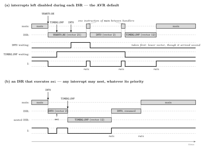
Figure 5: Two cases, each with the I bit traced underneath. (a) The default. While the USART0_RX handler runs, I is 0, so the timer overflow and then INT0 arrive and wait, their flags set (the two middle traces). When reti sets I again, the lower vector goes first: INT0 (vector 2) is serviced before TIMER2_OVF (vector 12) even though it arrived later. That ordering is the only thing priority does on the AVR. Between two handlers the CPU executes one instruction of main, as the datasheet specifies, so a steady stream of interrupts cannot starve the main program completely. (b) An ISR that executes sei early. From that instruction on, I is 1 and any interrupt is taken at once, however low its priority: the timer overflow nests inside the INT0 handler, and INT0’s handler finishes only after the nested one returns. The hardware saves nothing extra for the nesting; each level’s return address is simply one more pair of bytes on the stack.
The (b) case is sometimes exactly what is wanted. A long, unhurried handler can re-enable interrupts so that a time-critical source is not kept waiting. But it gives up the protection the default provides: the handler can now be interrupted by anything, including a second copy of itself if its own source fires again, and every level of nesting costs more stack. Nothing in the course’s labs needs it.
Traps
Traps are software interrupts: they are caused by events in software rather than hardware. The events are exceptional ones. Examples:
- overflow
- divide by zero
- undefined opcode
Traps save continually checking for errors. Trap handlers (service routines) don’t always return to the original program. The AVR doesn’t provide traps, but it is possible to generate hardware interrupts from software.
Traps are to error checking what interrupts are to polling. Without them, a program that cares about overflow has to test V after every addition, which is polling for errors. With them, the hardware watches, and the program is diverted only when the error actually happens. That a handler doesn’t always return follows from what the errors are: after a division by zero or an undefined opcode there is often no sensible instruction to continue with, and under an operating system the usual outcome is that the program is ended. On the AVR none of this exists. Overflow simply sets V for the program to test with a branch (avr-branches-and-jumps), and there is no divide instruction to fail. The hardware interrupts that software can generate are the external interrupt pins: the datasheet notes that INT0–INT2 still trigger when their pins are configured as outputs, so writing the pin’s PORT bit raises the interrupt on purpose.
See also
- polling-and-interrupts — polling versus interrupts, the fourteen-step sequence drawn, transparency, the three nesting policies, traps
- avr-interrupts — the ATmega324A vector table in full, the ISR template’s stack,
ISR()and the_vectnames, setting up an interrupt,volatile, a complete timer-interrupt program - procedures-and-the-stack —
push,pop,call,retand the stack pointer - avr-timers-and-counters —
TIMSKnandTIFRn, the timer interrupt registers - avr-program-structure — the
jmp RESETat the top of every program, and the vector table after it - avr-architecture — the status register and its I bit · avr-instructions — which instructions change the flags
- c-preprocessor-and-avr-headers —
volatileon the I/O register macros - 2026-09-14-flow-of-control — Lecture 15 · 2026-09-17-pulse-width-modulation — Lecture 16 · 2026-09-24-serial-io — Lecture 18 · 2026-10-05-more-io — Lecture 19,
volatileagain - week9-lab-avr-interrupts — Lab 14: interrupts in C on the board