Lecture 18 — Serial Input/Output
How a microcontroller talks to another computer over a single wire, and a first look at reading analog voltages. It covers serial against parallel and synchronous against asynchronous links, the UART frame with its start, data, parity and stop bits, how a receiver finds the bits with no shared clock, baud rate, and the ATmega324A’s USART: its registers and its three interrupts. The last part is the PC end of the link, RS232, and analog to digital conversion. The reference notes are serial-communication, avr-usart and analog-to-digital-conversion.
Where serial I/O fits
The parts of the ATmega324A used so far (avr-architecture):
| Part | What it has been used for |
|---|---|
| Ports A, B, C, D | switches, buttons and the seven-segment display (avr-io-ports, seven-segment-display) |
| CPU, flash, SRAM | running the program |
| Timer/counters 0, 1, 2 | timing, waveforms and PWM (avr-timers-and-counters) |
Three more blocks come into play from here:
- USART0 and USART1: two serial ports. A key typed in a terminal program on a PC travels down a wire and arrives in the microcontroller as a character, and the microcontroller can send characters back.
- SPI: the chip’s other serial interface, a synchronous one. It is the one that will drive the LED display.
- The A/D converter: reads a voltage, such as the position of a joystick, as a number.
The block diagram in the datasheet is shared by a family of chips and shows timers the 324A does not have. The 324A has exactly three: two 8-bit and one 16-bit.
Interrupt set-up, once more
A device can interrupt the CPU only when three things are true at once (avr-interrupts):
- Interrupts are enabled globally:
sei()has set the I bit, bit 7 ofSREG. - The device’s own interrupt is enabled: for a timer 1 compare match,
OCIE1AinTIMSK1. - The device’s interrupt flag is set:
OCF1AinTIFR1, set by the hardware when the event happens.
The set-up code makes the first two true and leaves them that way. The third is different, because the flag is set by the hardware, at the moment of the event. Set-up does two things about it. It configures the device so that the event will happen: for the timer that is the mode, the prescaler and a compare value such as OCR1A = 200, after which the flag is set every time the count reaches 200. And it clears the flag first, so that an event from before the program was ready does not fire the handler straight away. Clearing it is the step that reads backwards.
An interrupt flag is cleared by writing a 1 to it. Writing a 0 does nothing.
Check. Which of these is false when configuring interrupt-driven I/O?
- A. Global interrupts should be enabled
- B.
SREGbit 7 should be set to 1 - C. The interrupt should be enabled in the I/O device
- D. A 1 should be written to the particular interrupt flag bit
- E. A 0 should be written to the particular interrupt flag bit
E. A and B are the same statement, since bit 7 of SREG is the global enable. C is the device’s enable bit. D is how a flag is cleared.
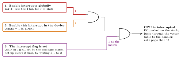
Figure 1: What has to be true for a timer compare match to interrupt the CPU, as the inputs of two AND gates. The set-up code puts the first two lines at 1 and they stay there. The third line is the flag, which the timer sets at each compare match, so the output goes to 1 only when the event happens. Without the first or the second the handler never runs. Set-up also clears the flag to begin with, by writing a 1 to it, so that an old event cannot run the handler straight away.
When the interrupt is taken, the address of the next instruction is pushed on the stack, the CPU jumps through the vector table to the handler, and reti pops the address to resume (procedures-and-the-stack).
Serial and parallel, synchronous and asynchronous
Two independent choices describe a communication link.
Serial or parallel is about how many wires carry data. A parallel link has one wire per bit and sends the bits together. A serial link has one wire, and the bits take turns. Serial needs fewer pins and wires, which is why almost every link between devices is serial.
Synchronous or asynchronous is about how the receiver knows when to look at the wire. A synchronous link sends a clock on a second wire alongside the data. An asynchronous link has no clock wire, so the receiver must recover the timing from the data itself, and the data must be encoded to make that possible.
| Example | |
|---|---|
| synchronous serial | SPI, Serial Peripheral Interface |
| asynchronous serial | UART, Universal Asynchronous Receiver and Transmitter; USB |
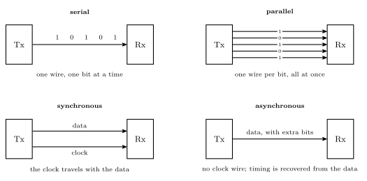
Figure 2: Four ways to join a transmitter to a receiver. Top row: the same five bits sent serially, one after another down a single wire, and in parallel, on five wires at once. Bottom row: two kinds of serial link. A synchronous link has a second wire carrying the clock that says when each data bit is valid. An asynchronous link has the data wire only, and the transmitter adds extra bits to the stream so that the receiver can work out the timing for itself.
The difficulty with no clock wire is that a run of identical bits is a flat line with nothing to time against. The encodings in use are different ways of guaranteeing edges:
- Start and stop bits: every character begins with a guaranteed edge. This is what a UART does.
- 4B/5B and 8B/10B: every 4 or 8 bits are sent as a 5- or 10-bit code chosen so that the line changes often.
- Bit stuffing: an opposite bit is inserted after a run of identical ones. USB at low and full speed does this.
The UART frame
The AVR’s serial port is a USART, a Universal Synchronous and Asynchronous Receiver/Transmitter. It can do both, and the course uses it mainly in asynchronous mode, so it is usually just called a UART. Three things characterise it:
- It is serial: data goes one bit at a time, in groups called frames.
- It is asynchronous: no clock is sent. Each end has its own clock. The two clocks can be quite different, as long as each end can derive nearly the same bit time from its own.
- It uses start and stop bits to mark each frame.
A frame is one character’s worth of data wrapped in framing bits, in this order:
| Field | Bits | Value |
|---|---|---|
| start bit | 1 | always 0 |
| data bits | 5 to 9 | the data, bit 0 first |
| parity bit | 0 or 1 | computed from the data; optional |
| stop bits | 1 or 2 | always 1 |
Between frames the line idles at 1. So a start bit is always a fall from 1 to 0, which is the event the receiver waits for, and the stop bit puts the line back at 1 so that the next start bit is a fall too. After the stop bit, either the next frame starts at once or the line stays idle.
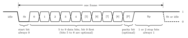
Figure 3: One UART frame, field by field. The line idles at 1. The start bit is always 0, so every frame begins with a falling edge. The data bits follow, least significant first: there are at least five and at most nine. The parity bit is optional. One or two stop bits, always 1, end the frame and return the line to its idle level, ready for the falling edge of the next start bit.
Parity
The parity bit is for error detection. Both ends agree on even or odd parity beforehand.
- Even parity: the number of 1s in the data bits plus the parity bit must be even.
- Odd parity: that number must be odd.
The transmitter works out the parity bit and sends it. The receiver counts the 1s in everything it received, parity bit included, and a count of the wrong kind means at least one bit was changed on the way.
Example. Nine data bits 0 0 1 0 0 1 1 1 1 contain five 1s. For even parity the parity bit is 1, making six. For odd parity it is 0, leaving five.
Check. 0xA7 is to be sent as 8 data bits with odd parity. What is the parity bit? 0xA7 is 1010 0111: two 1s and three 1s, five in all. Five is already odd, so the parity bit is 0.
Check. 0xA9 arrives with parity bit 1 on a link using even parity. Was there an error? 0xA9 is 1010 1001, four 1s. With the parity bit that is five, which is odd. Yes: at least one of the nine bits is not what was sent.
Parity can say that something went wrong. It cannot say which bit, and if two bits flip the count comes out right again and the error goes unnoticed. Finding and repairing the wrong bit is error correction, which takes more check bits arranged as a Hamming code and is not part of a UART frame.
How the receiver finds the bits
The receiver has to know the baud rate in advance, but its clock does not have to be synchronised with the transmitter’s. It works like this:
- It samples the line much faster than the bits arrive: 16 samples per bit on the AVR (8 in double-speed mode).
- The fall of the start bit starts it counting samples.
- It reads each bit from the three samples in the middle of that bit’s time, by majority vote. Three 0s in the middle of the first bit time confirm a real start bit and not a spike of noise.
Reading in the middle is what makes an unsynchronised clock tolerable. If the receiver’s bit time is a little long or short, its sampling point drifts a little further with every bit, and starting from the centre leaves half a bit of margin either way. The drift has only one frame to build up before the next start bit resets it.
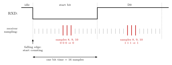
Figure 4: How a UART receiver reads a bit without a shared clock. It samples the line 16 times per bit. The falling edge of the start bit starts the count, and each bit is decided by a majority vote of the three samples at its centre, shown tall. Three 0s in the middle of the first bit time confirm a start bit. The same three positions in the next bit time read 1, 1, 1, so the first data bit is 1. Because the count restarts at every start bit, the two ends only have to agree on the bit time closely enough for the sampling point to stay inside the bit for one frame.
Baud rate
Baud rate = symbols per second. It is not the same as the bit rate, the number of useful data bits per second.
Every bit time on the wire is one symbol, whether it carries data or framing. With 8 data bits, no parity, one start bit and one stop bit, a frame is 10 symbols and carries 8 bits:
\[9600 \text{ baud} \times \tfrac{8}{10} = 7680 \text{ bits per second} = 960 \text{ bytes per second}\]
The industry-standard rates are 2400, 4800, 9600, 14400, 19200, 28800, 38400, 57600 and 115200.
On the AVR the rate is set by a number in the baud-rate register, worked out from the clock frequency and the 16 samples per symbol:
\[UBRRn = \frac{f_{OSC}}{16 \cdot BAUD} - 1\]
For 9600 baud with the 8 MHz clock: \(8\,000\,000 / (16 \times 9600) - 1 = 51.08\), so the register is 51. The real rate is then \(8\,000\,000 / (16 \times 52) = 9615\) baud, about 0.2 % fast, which is easily close enough. The datasheet tabulates the values for the standard rates (pages 198 to 201), and avr-usart works them out. The formula has the same shape as the timer’s master formula (avr-timers-and-counters) for the same reason: counting through the values 0 to \(N\) takes \(N + 1\) clock cycles, here with \(N = UBRR\).
The AVR USART
USART0 uses two pins of port D: PD0 is RXD0, receive, and PD1 is TXD0, transmit. The USART is described on pages 175 to 201 of the datasheet.
At the centre of each half is a shift register (shift-registers). To transmit, a byte written to the data register is loaded into the transmit shift register and shifted out of TxD one bit per bit time, with the framing bits added. To receive, bits arriving on RxD are shifted in one at a time, and the completed byte is copied to the data register. A UART is a parallel-to-serial converter and a serial-to-parallel converter with framing.
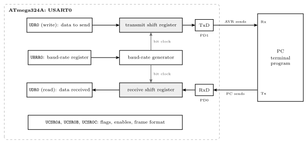
Figure 5: The USART reduced to what a program uses, joined to a PC. The baud-rate register sets the bit time for both halves. A byte written to the data register is copied into the transmit shift register and shifted out of the TxD pin, with the start, parity and stop bits added on the way. Bits arriving on RxD are shifted into the receive shift register, checked and stripped of their framing, and the byte is copied to the data register to be read. The two ends are cross-connected: each one’s transmit pin goes to the other’s receive pin.
A program works the USART through five I/O registers.
UDR0, the data register. One name, two registers: writing UDR0 puts a byte in the transmit buffer, and reading UDR0 takes a byte from the receive buffer. Reading it does not give back what was last written.
UCSR0A, UCSR0B, UCSR0C, the control and status registers.
| 7 | 6 | 5 | 4 | 3 | 2 | 1 | 0 | |
|---|---|---|---|---|---|---|---|---|
UCSR0A |
RXC0 |
TXC0 |
UDRE0 |
FE0 |
DOR0 |
UPE0 |
U2X0 |
MPCM0 |
UCSR0B |
RXCIE0 |
TXCIE0 |
UDRIE0 |
RXEN0 |
TXEN0 |
UCSZ02 |
RXB80 |
TXB80 |
UCSR0C |
UMSEL01 |
UMSEL00 |
UPM01 |
UPM00 |
USBS0 |
UCSZ01 |
UCSZ00 |
UCPOL0 |
The pattern that makes these readable:
- The top three bits of A are the interrupt flags: receive complete, transmit complete, data register empty.
- The top three bits of B, directly beneath them, are the matching interrupt enables. IE in each name is interrupt enable.
- C holds the frame format:
UPMselects the parity (none, even or odd) andUSBSselects one or two stop bits.
After reset, C is set for 8 data bits, no parity and one stop bit, the commonest format. Every bit is explained in avr-usart.
UBRR0, the baud-rate register. A 12-bit value held in two bytes, UBRR0H and UBRR0L. Either compute it from the formula or take it from the datasheet’s tables.
The three serial interrupts
Each serial port has three interrupt sources.
| Interrupt | Means |
|---|---|
| Receive complete | a frame, usually a character, has arrived and can be read |
| Transmit complete | a frame has been sent and no more data is waiting to go |
| Data register empty | the port is ready to accept another byte for transmission |
The last two are easy to confuse. The USART can hold two bytes on the way out: one in the shift register being sent, and one in the data register waiting. Data register empty means the waiting place is free, so the next byte can be written even though the previous one is still going out. Transmit complete means the last bit has left and nothing was waiting, so the line has gone idle.
The PC end
A PC has no UART pins. The IO board (io-board) has a USB-serial device on it, which appears to the PC as a serial port and presents the two serial lines to the breadboard. On the PC a terminal program such as PuTTY sends what is typed and shows what arrives. It has to be told:
- the COM port, which serial port to use (Device Manager shows which one the board has been given);
- the baud rate and the frame format: data bits, parity, stop bits.
Nothing on the wire announces these settings, so the two ends must simply be set the same. A mismatch gives wrong characters, not an error message.
RS232
RS232 is the long-established serial standard, more than forty years old and still in use, typically on a 9-pin D-sub connector. It carries the same frames at different voltages:
| AVR pin | RS232 | |
|---|---|---|
| logical 1 | 5 V | a negative voltage, −3 to −15 V |
| logical 0 | 0 V | a positive voltage, +3 to +15 V |
The levels are inverted as well as larger, so a converter chip such as the MAX-232 is needed between the two. RS232 is full duplex: it can transmit and receive at the same time, because each direction has its own wire. The minimum connection is three signals: transmit data (TxD), receive data (RxD) and ground.
Analog to digital conversion
Every input so far has been digital: the processor sees 0 or 1. An analog to digital converter (ADC) takes a voltage anywhere between 0 and a maximum, the reference voltage \(V_{ref}\), and turns it into a number in proportion.
An ADC has a resolution, the number of bits in its result. With 10 bits there are \(2^{10} = 1024\) possible results, 0 to 1023.
A joystick is the standard example. It produces two voltages, one for each direction of travel, and after conversion its position is a pair of numbers.
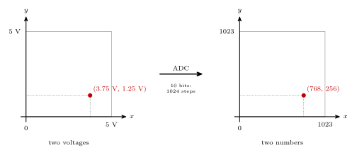
Figure 6: What a 10-bit converter does to a joystick. Left: the stick’s position as two voltages, each between 0 V and the reference, here 5 V. Right: the same position after conversion, as two numbers from 0 to 1023. The converter divides the range of each voltage into 1024 equal steps, about 4.9 mV each, and reports which step the voltage is on. The marked position, 3.75 V across and 1.25 V up, becomes 768 and 256.
On the ATmega324A:
- The port A pins can be used as analog inputs.
- One input is converted at a time. An analog multiplexer selects which pin is connected to the converter, so a joystick’s two voltages are read one after the other.
- \(V_{ref}\) can be chosen. The course uses \(V_{cc} = 5\ \text{V}\).
- The resolution is 10 bits, 0 to 1023.
- A conversion takes time: up to 3200 clock cycles, 0.4 ms at 8 MHz. Accuracy can be traded for speed.
0.4 ms is long enough for a couple of thousand instructions, so the end of a conversion is another event a program either polls for or takes as an interrupt (polling-and-interrupts). More in analog-to-digital-conversion.
See also
- serial-communication — serial and parallel, synchronous and asynchronous, the UART frame, parity, sampling, baud rate, RS232
- avr-usart — the USART’s registers bit by bit, the baud-rate values, code for sending and receiving, and the three interrupts
- analog-to-digital-conversion — resolution, the reference voltage, and the ATmega324A’s converter
- avr-interrupts · polling-and-interrupts — flags, enables and the global enable
- shift-registers — the conversion between parallel and serial at the centre of a UART
- avr-architecture — the block diagram · io-board — the USB-serial device
- avr-spi — SPI, the synchronous serial port, which drives the LED matrix
- 2026-09-21-interrupts — Lecture 17 · 2026-10-05-more-io — Lecture 19