The AVR USART
The ATmega324A’s serial port: the pins, the five registers a program uses, how to set the baud rate, how to send and receive a byte, and the three interrupts. What a UART frame is, and what baud rate and parity mean, are in serial-communication. First met in 2026-09-24-serial-io. The datasheet covers the USART on pages 175 to 201.
What it is
A USART is a Universal Synchronous and Asynchronous Receiver/Transmitter. The course uses it in its asynchronous mode, as a UART: frames with start and stop bits, no clock wire.
The ATmega324A has two, USART0 and USART1. USART0’s pins are on port D:
| Pin | Name | Direction |
|---|---|---|
| PD0 | RXD0 |
receive: data coming in |
| PD1 | TXD0 |
transmit: data going out |
Turning the receiver or transmitter on takes its pin away from the port, in the same way a timer takes over its output-compare pin (avr-timers-and-counters).
The registers
| Register | Holds |
|---|---|
UDR0 |
the data: write a byte to send it, read to collect a received byte |
UCSR0A |
status flags, and two mode bits |
UCSR0B |
interrupt enables, receiver and transmitter enables |
UCSR0C |
the frame format |
UBRR0 (UBRR0H, UBRR0L) |
the baud rate |
The 0 in each name is the USART number. The datasheet writes the names with an n in its place, as in UDRn.
The data register
UDR0 is two registers at one address. A write goes to the transmit buffer. A read comes from the receive buffer. So
UDR0 = 'A';        /* send the letter A            */
c = UDR0;          /* collect whatever has arrived */
and reading UDR0 never returns the value that was written to it.
Behind each buffer is a shift register (shift-registers). A byte written to UDR0 waits there until the transmit shift register is free, is copied across, and is shifted out of TXD0 bit by bit, with the start bit, any parity bit and the stop bits added. On the way in, bits from RXD0 are shifted into the receive shift register, and the finished byte is copied to the receive buffer.
That makes the transmitter two bytes deep: one byte going out and one waiting behind it. It is why there are two separate “finished” conditions, below.
Control and status registers
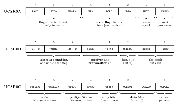
Figure 1: The three control and status registers of USART0, with their bits grouped by what they do. The top three bits of UCSR0A are the flags for the three serial events, and the top three bits of UCSR0B, directly beneath, are the interrupt enables for the same three events in the same order. UCSR0B also switches the receiver and transmitter on. UCSR0C sets the frame format. The number of data bits is the one setting split across two registers: UCSZ02 is in UCSR0B and UCSZ01:00 are in UCSR0C.
UCSR0A: what has happened
| Bit | Name | Set when | Cleared by |
|---|---|---|---|
| 7 | RXC0 |
receive complete: a byte has arrived and has not been read | reading UDR0 |
| 6 | TXC0 |
transmit complete: a frame has been sent and nothing is waiting | its interrupt running, or writing a 1 to it |
| 5 | UDRE0 |
data register empty: UDR0 can take another byte |
writing UDR0 |
| 4 | FE0 |
frame error: the stop bit of the received frame was 0 | the next read of UDR0 |
| 3 | DOR0 |
data overrun: a byte arrived with no room left for it and was lost | the next read of UDR0 |
| 2 | UPE0 |
parity error in the received frame | the next read of UDR0 |
| 1 | U2X0 |
(a setting) 1 doubles the speed: 8 samples per bit, not 16 | |
| 0 | MPCM0 |
(a setting) multi-processor mode, not used here |
After reset UDRE0 is 1, because the transmit buffer starts empty, and every other bit is 0. The three error flags describe the byte currently waiting in UDR0, so they must be read before UDR0.
UCSR0B: what is switched on
| Bit | Name | When 1 |
|---|---|---|
| 7 | RXCIE0 |
the receive-complete flag raises an interrupt |
| 6 | TXCIE0 |
the transmit-complete flag raises an interrupt |
| 5 | UDRIE0 |
the data-register-empty flag raises an interrupt |
| 4 | RXEN0 |
the receiver is on, and PD0 belongs to it |
| 3 | TXEN0 |
the transmitter is on, and PD1 belongs to it |
| 2 | UCSZ02 |
top bit of the data-bits setting (1 only for 9 data bits) |
| 1 | RXB80 |
the ninth data bit of a received 9-bit frame |
| 0 | TXB80 |
the ninth data bit to send in a 9-bit frame |
All 0 after reset: the USART does nothing until RXEN0 or TXEN0 is set.
UCSR0C: the frame format
| Bits | Name | Setting |
|---|---|---|
| 7:6 | UMSEL01:00 |
mode. 00 asynchronous, the one used here |
| 5:4 | UPM01:00 |
parity. 00 none, 10 even, 11 odd |
| 3 | USBS0 |
stop bits. 0 one, 1 two |
| 2:1 | UCSZ01:00 |
data bits, with UCSZ02: 000 5, 001 6, 010 7, 011 8, 111 9 |
| 0 | UCPOL0 |
clock polarity, synchronous mode only |
After reset this register holds UCSZ01:00 = 11 and 0 elsewhere, which is 8 data bits, no parity, 1 stop bit. A program that wants 8N1 does not need to write UCSR0C at all.
Setting the baud rate
\[UBRR0 = \frac{f_{OSC}}{16 \cdot BAUD} - 1\]
\(f_{OSC}\) is the clock, 8 MHz. This is the formula for asynchronous normal mode, the one the course uses, in which the receiver takes 16 samples per bit, and that is where the 16 comes from. The \(-1\) is there because the baud-rate generator counts from UBRR0 down to 0, which is \(UBRR0 + 1\) clock cycles per sample. UBRR0 is 12 bits wide, so 0 to 4095.
The result is rarely a whole number. Round it to the nearest, then work out what rate that really gives, \(f_{OSC} / (16 \cdot (UBRR0 + 1))\), and how far off it is.
| Baud rate | \(\dfrac{8\,000\,000}{16 \cdot BAUD} - 1\) | UBRR0 |
Actual rate | Error |
|---|---|---|---|---|
| 2400 | 207.3 | 207 | 2404 | +0.2 % |
| 4800 | 103.2 | 103 | 4808 | +0.2 % |
| 9600 | 51.1 | 51 | 9615 | +0.2 % |
| 14400 | 33.7 | 34 | 14286 | −0.8 % |
| 19200 | 25.0 | 25 | 19231 | +0.2 % |
| 28800 | 16.4 | 16 | 29412 | +2.1 % |
| 38400 | 12.0 | 12 | 38462 | +0.2 % |
| 57600 | 7.7 | 8 | 55556 | −3.5 % |
| 115200 | 3.3 | 3 | 125000 | +8.5 % |
The receiver tolerates an error of a few percent (serial-communication), so the rates up to 38400 are all within about 2 % at 8 MHz and work, with 28800 the closest to the limit. 57600 is marginal and 115200 does not work. The faster the rate, the fewer clock cycles there are per bit and the coarser the choice of rates becomes. The datasheet has the same table on pages 198 to 201.
In C the register is written in one assignment and the compiler handles the two bytes:
UBRR0 = 51; /* 9600 baud at 8 MHz */Sending and receiving, by polling
The smallest complete program: 9600 baud, 8N1, echo every character back.
#include <avr/io.h>

int main(void) {
    uint8_t c;

    UBRR0  = 51;                          /* 9600 baud at 8 MHz              */
    UCSR0B = (1<<RXEN0) | (1<<TXEN0);     /* receiver and transmitter on     */
                                          /* UCSR0C left at reset: 8N1       */
    while (1) {
        while (!(UCSR0A & (1<<RXC0))) {   /* wait for a byte to arrive       */
        }
        c = UDR0;                         /* collect it (this clears RXC0)   */

        while (!(UCSR0A & (1<<UDRE0))) {  /* wait for room in the data reg.  */
        }
        UDR0 = c;                         /* send it back                    */
    }
}
The two rules it follows:
- Before reading
UDR0, checkRXC0. If nothing has arrived there is nothing to read. - Before writing
UDR0, checkUDRE0. A write while the previous byte is still waiting is ignored, so the new byte is never sent.
Both loops are polling (polling-and-interrupts): the processor does nothing else while it waits. At 9600 baud a frame takes about a millisecond to go out, more than 8000 clock cycles.
The three interrupts
| Event | Flag (UCSR0A) |
Enable (UCSR0B) |
Handler |
|---|---|---|---|
| receive complete | RXC0 |
RXCIE0 |
ISR(USART0_RX_vect) |
| data register empty | UDRE0 |
UDRIE0 |
ISR(USART0_UDRE_vect) |
| transmit complete | TXC0 |
TXCIE0 |
ISR(USART0_TX_vect) |
They are vectors 21, 22 and 23, in that order, so receive has the highest priority of the three (avr-interrupts).
Data register empty or transmit complete? They mark different moments, because the transmitter holds two bytes.
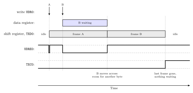
Figure 2: Sending two bytes, A then B, one straight after the other. A moves from the data register into the shift register as soon as it is written, so UDRE0 drops only for an instant and B can be written while A is still on the wire. B then waits in the data register, UDRE0 staying at 0, until A’s stop bit has gone, when it moves across and UDRE0 returns to 1. TXC0 is set only at the very end: the last frame has left and no byte is waiting behind it.
- Use data register empty to keep data flowing: each time it fires, hand over the next byte.
- Use transmit complete when the program needs to know the line has gone quiet, for example before switching the transmitter off.
Receiving by interrupt. The handler runs once per byte, and reading UDR0 is what clears the flag:
#include <avr/io.h>
#include <avr/interrupt.h>

ISR(USART0_RX_vect) {
    uint8_t c = UDR0;                     /* reading clears RXC0             */
    UDR0 = c;                             /* echo (assumes room, see below)  */
}

int main(void) {
    UBRR0  = 51;
    UCSR0B = (1<<RXEN0) | (1<<TXEN0) | (1<<RXCIE0);
    sei();
    while (1) {
        /* free to do anything else */
    }
}
A handler that does not read UDR0 leaves RXC0 set, and it is called again the moment it returns, for ever. The echo here is safe because bytes cannot arrive faster than they can be sent back at the same baud rate.
UDRIE0 needs care. The data register is empty most of the time, so its flag is nearly always set. Enabling the interrupt with nothing to send calls the handler continuously. The pattern is to enable UDRIE0 when there is data queued and have the handler disable it again when the queue runs out.
Common mistakes
- Reading
UDR0to see what was written. Reads and writes go to different registers. - Forgetting
RXEN0orTXEN0. The baud rate and format can be perfect and nothing happens. - Forgetting the \(-1\) in the baud-rate formula, giving 52 for 9600 instead of 51.
- Writing
UDR0without checkingUDRE0, which loses bytes when sending more than one. - Reading
UDR0before the error flags. The flags belong to the byte being read and are gone afterwards. - A receive handler that does not read
UDR0. - Leaving
UDRIE0enabled with nothing to send. - Mismatched settings at the two ends. The symptom is garbled characters, not silence (serial-communication).
See also
- serial-communication — frames, parity, sampling, baud rate against bit rate, RS232
- avr-interrupts — flags, enables, the vector table and writing a handler in C
- polling-and-interrupts — waiting on a flag against being interrupted by it
- avr-timers-and-counters — the master formula the baud-rate formula mirrors
- shift-registers — the heart of the transmitter and the receiver
- bit-masking · c-preprocessor-and-avr-headers —
(1<<RXEN0)and where the names come from - io-board — the USB-serial device at the other end of the wires
- avr-spi — the SPI port, and the USART as an SPI master when
UMSELn1:0=11 - 2026-09-24-serial-io — Lecture 18