Serial Communication
Sending data between devices one bit at a time, and how the receiving end makes sense of what arrives: serial against parallel, synchronous against asynchronous, the UART frame, parity, how a receiver samples the line, and baud rate. Then the synchronous serial buses, where one master clocks data to and from several slaves: SPI and I²C, compared with the UART, and bit bashing for when there is no hardware for a standard. The AVR’s hardware is in avr-usart and avr-spi. First met in 2026-09-24-serial-io and 2026-10-05-more-io.
Serial and parallel
| Parallel | Serial | |
|---|---|---|
| Wires carrying data | one per bit | one |
| How a byte travels | all 8 bits at once | 8 bits one after another |
| Cost | many pins and wires | time: a byte takes 8 bit times |
Inside a chip, data moves in parallel: a port is eight pins, a register is eight flip-flops. Between devices, pins and wires are what is scarce, so nearly every link is serial. The conversion at each end is the job of a shift register (shift-registers): load a byte in parallel and shift it out one bit at a time to send, shift bits in and read the byte out in parallel to receive.
By convention the sending end of a link is Tx and the receiving end is Rx. A device that does both has one of each, and two such devices are joined crossed over: each one’s Tx goes to the other’s Rx.
Synchronous and asynchronous
A receiver has to know when to look at the data wire, as well as what is on it. There are two ways to tell it.
Synchronous: one end sends a clock on a second wire. The receiver reads the data wire on each clock edge. Nothing has to be agreed in advance about speed, beyond the fastest the receiver can follow. SPI, the Serial Peripheral Interface, and I²C both work this way (below).
Asynchronous: there is no clock wire. Each end has its own clock, the two agree on the speed beforehand, and the receiver recovers the exact timing from the data stream itself. That only works if the stream is guaranteed to contain edges to time against, so the data is encoded:
| Encoding | How it guarantees edges | Used by |
|---|---|---|
| start and stop bits | every character begins with a fall from 1 to 0 | UART |
| 4B/5B, 8B/10B | every 4 or 8 bits are replaced by a 5- or 10-bit code that never has a long run | fast network links |
| bit stuffing | an opposite bit is inserted after a run of identical bits | USB at low and full speed |
A UART is a Universal Asynchronous Receiver and Transmitter. A USART can also work synchronously. The pictures of all four cases are in 2026-09-24-serial-io.
The UART frame
A UART sends data in frames. Between frames the line rests at 1, the idle level. A frame is:
| Order | Field | How many | Value |
|---|---|---|---|
| 1 | start bit | 1 | always 0 |
| 2 | data bits | 5 to 9 | the data, least significant bit first |
| 3 | parity bit | 0 or 1 | chosen to make the count of 1s even or odd |
| 4 | stop bits | 1 or 2 | always 1 |
Why each part is there:
- The start bit is 0 because the idle line is 1. The fall from 1 to 0 is the one event the receiver can be sure of, and everything else is timed from it.
- The stop bit is 1 so that the line is back at the idle level when the frame ends. Whatever the last data bit was, the next start bit is then a fall again.
- The data bits go least significant first. A receiver that assumes the opposite reads every byte bit-reversed.
The format is usually written as three items: data bits, parity (N for none, E for even, O for odd), stop bits. 8N1 is 8 data bits, no parity, 1 stop bit, and is by far the commonest.
Worked: the letter s
A character is sent as its ASCII code (c-language-basics). The letter s is 115, 0x73, 0111 0011. In 8N1 the line carries, in time order:
| start | b0 | b1 | b2 | b3 | b4 | b5 | b6 | b7 | stop |
|---|---|---|---|---|---|---|---|---|---|
| 0 | 1 | 1 | 0 | 0 | 1 | 1 | 1 | 0 | 1 |
Read left to right, the data bits are 1100 1110, the byte written backwards.
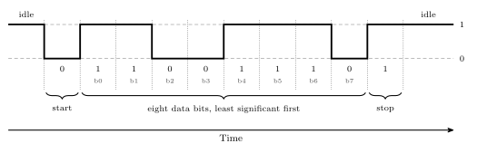
Figure 1: The letter s, 0x73, on the wire as an 8N1 frame. Time runs left to right and each cell is one bit time. The line idles at 1, falls for the start bit, carries the eight data bits least significant first, and returns to 1 for the stop bit. Written most significant bit first the byte is 0111 0011; the wire carries it in the opposite order.
Parity
The parity bit lets the receiver detect that a frame was damaged. The two ends agree on the kind:
- Even parity: the number of 1s in the data bits and the parity bit together is even.
- Odd parity: that number is odd.
To send: count the 1s in the data. Choose the parity bit that makes the total the agreed kind.
To check: count the 1s in the data and the parity bit as received. If the total is the wrong kind, there was an error.
| Data | 1s in the data | Even parity bit | Odd parity bit |
|---|---|---|---|
0xA7 = 1010 0111 |
5 | 1 | 0 |
0xA9 = 1010 1001 |
4 | 0 | 1 |
0x73 = 0111 0011 |
5 | 1 | 0 |
0x00 = 0000 0000 |
0 | 0 | 1 |
The even parity bit is the XOR of the data bits (logic-gates): XOR is 1 exactly when an odd number of its inputs are 1, which is exactly when a 1 is needed to make the total even. The odd parity bit is its complement.
Worked check. 0xA9 arrives with parity bit 1 on an even-parity link. The data has four 1s, and the parity bit makes five. Five is odd, so the frame is in error.
What parity cannot do:
- It cannot say which bit is wrong, so it cannot correct anything. The frame has to be discarded or sent again.
- It misses any even number of flipped bits. Two flips cancel and the count comes out right.
Detecting and correcting needs several check bits arranged so that the pattern of failed checks points at the wrong bit. That is a Hamming code, and it is not part of a UART frame.
Sampling: finding the bits without a clock
The receiver knows the bit time from the agreed baud rate. What it does not know is when a frame will start. It finds out by watching:
- It samples the line many times per bit: 16 on the AVR.
- While the line is idle, every sample is 1. A sample of 0 means a start bit may have begun, and the receiver starts counting samples from there.
- It reads the three samples at the centre of each bit time and takes the majority. For the first bit time the answer must be 0, or the fall was only noise and the receiver goes back to waiting.
- It carries on, one bit time after another, for the data bits, the parity bit if there is one, and the stop bit.
- The stop bit must read 1. If it reads 0 the frame is wrong: a framing error, usually a sign that the two ends disagree about the baud rate or the format.
The picture is in 2026-09-24-serial-io.
Why the clocks need not match exactly. Suppose the receiver’s clock is slightly slow. Each sampling point is then a little later within its bit than the one before, and by the last bit of the frame the lateness has added up. As long as the total stays under half a bit time, every sample still lands inside the right bit. A 10-symbol frame gives the error about ten bit times to build up, so the two clocks have to agree to within a few percent. At the next start bit the count starts again from the new falling edge and the accumulated error is gone. That re-timing on every frame is what the start bit is for.
Baud rate and bit rate
Baud rate = symbols per second. Bit rate = useful data bits per second.
On a UART line a symbol is one bit time, and start, parity and stop bits are symbols that carry no data. So the bit rate is always lower than the baud rate, by the fraction of the frame that is data.
| Format | Symbols per frame | Data bits | Data fraction | At 9600 baud |
|---|---|---|---|---|
| 8N1 | 10 | 8 | 80 % | 7680 bit/s, 960 bytes/s |
| 8E1 or 8O1 | 11 | 8 | 73 % | 6982 bit/s, 873 bytes/s |
| 8N2 | 11 | 8 | 73 % | 6982 bit/s, 873 bytes/s |
| 7E1 | 10 | 7 | 70 % | 6720 bit/s, 960 characters/s |
The method: frames per second is the baud rate divided by the symbols per frame, and bits per second is that times the data bits per frame. For 8N1 at 9600 baud, \(9600 / 10 = 960\) frames per second and \(960 \times 8 = 7680\) bits per second.
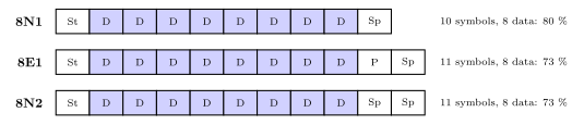
Figure 2: Three frame formats, one cell per symbol. Shaded cells carry data and white cells are framing. Every format here carries eight data bits, so adding a parity bit or a second stop bit makes the frame eleven symbols long instead of ten, and at the same baud rate fewer frames fit into a second.
The standard baud rates are 2400, 4800, 9600, 14400, 19200, 28800, 38400, 57600 and 115200.
Both ends must agree
Four settings define a UART link, and none of them is sent over it:
- the baud rate;
- the number of data bits;
- the parity: none, even or odd;
- the number of stop bits.
A terminal program on a PC asks for all four, plus which serial port to use. If the two ends differ, the receiver still samples the line and still produces bytes. They are just the wrong bytes, sometimes with framing or parity errors flagged and sometimes not. Garbled characters on a terminal almost always mean a mismatch here, most often the baud rate.
RS232
A serial standard more than 40 years old and still in use, typically on a 9-pin D-sub connector. Its frames are UART frames. Its voltages are not the microcontroller’s:
| Microcontroller pin | RS232 line | |
|---|---|---|
| logical 1 | 5 V | negative, −3 V to −15 V |
| logical 0 | 0 V | positive, +3 V to +15 V |
So RS232 is inverted and uses larger voltages of both signs. A level-converter chip such as the MAX-232 goes between an AVR pin and an RS232 line. Connecting the two directly does not work and can damage the pin.
RS232 is full duplex: there is a separate wire for each direction, so both ends can transmit at once. The standard defines many signals, and the smallest useful set is three: TxD, RxD and ground. Ground is needed because a voltage only has meaning against a reference both ends share.
Buses: masters and slaves
A UART joins exactly two devices. A bus is a set of wires shared by several, and that raises the question of who decides when a transfer happens.
- The master initiates and controls the transfer of data: it decides when a transfer starts, which device it is with and which way the data goes, and on a synchronous bus it drives the clock.
- A slave waits for requests and responds to the master. It never starts a transfer.
Some devices can be both, at different times. The AVR’s SPI and TWI ports can each be set up as a master or as a slave, and on an I²C bus more than one device may take a turn at being master. Memory can never be a bus master: all a memory can do is answer a read or a write of an address that something else has chosen. On a processor’s memory bus the CPU is the master.
Synchronous serial buses
Both buses here send a clock from the master alongside the data, so neither needs start and stop bits or an agreed baud rate. They differ in how the master picks which slave it is talking to.
SPI
The Serial Peripheral Interface has four signals: the clock SCK, a data wire each way, MOSI (master out, slave in) and MISO (master in, slave out), and an active-low select \(\overline{\text{SS}}\) for each slave. The master and the slave each hold an 8-bit shift register, and MOSI and MISO join them into a ring, so on every clock pulse one bit goes each way. Eight pulses swap the two bytes: every transfer is an exchange. Several slaves either get a select line each, or are daisy-chained on one select with the data passing through each in turn. All of this, with the AVR’s SPI port, is in avr-spi.
I²C and TWI
I²C, the Inter-Integrated Circuit bus, was created by Philips Semiconductor, now NXP. TWI, the Two-wire Interface, is Atmel’s name for it. There are two wires, and every device connects to both:
- SDA, serial data, which carries data in either direction, one way at a time;
- SCL, serial clock, driven by the master.
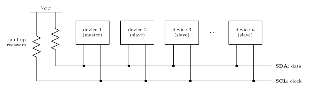
Figure 3: An I²C bus. Every device connects to the same two wires: SDA carries the data, in either direction, and SCL carries the clock from the master. No device ever drives a line high. Each can only pull a line low or let go of it, and the two pull-up resistors hold a line at 1 while nobody is pulling, so two devices can never fight over a line. Because every device hears every transfer, the master begins each one with the address of the slave it is for. A dot is a connection; where a lead crosses SDA without a dot there is no connection.
Why the pull-ups. Every output on the bus is open drain: it can connect its line to ground or leave it alone, and never connects it to \(V_{CC}\). A line is 1 when nobody is pulling it down and 0 when anybody is. Any number of devices can share a wire that way without two outputs ever fighting.
Addresses instead of select lines. Every device sees every transfer, so the master starts each one by sending the address of the slave it wants, and only that slave answers. Adding a device adds no wires.
On the ATmega324A the TWI uses PC0 as SCL and PC1 as SDA, and the datasheet describes it on pages 211 to 239 (2026-10-05-more-io).
UART, SPI and I²C compared
| UART | SPI | I²C / TWI | |
|---|---|---|---|
| Clock | none: both ends agree a baud rate | SCK, from the master | SCL, from the master |
| Data wires | TxD and RxD, one each way | MOSI and MISO, one each way | SDA, shared by both directions |
| Both directions at once? | yes | yes: every transfer is an exchange | no |
| Devices | two | one master, many slaves | many, some able to be master |
| Choosing a slave | no need: only two ends | a select line per slave, or a daisy chain | an address sent on the bus |
| Wires, besides ground | 2 | 3, plus a select per slave | 2 |
| On the ATmega324A | USART0 (PD0, PD1), USART1 (PD2, PD3) | one SPI port, PB4 to PB7 | one TWI port, PC0 and PC1 |
Bit bashing
Sometimes a microcontroller has no hardware support for a bus standard, or not enough interfaces of it. The standard can still be used by simulating it on general purpose port pins: the program sets and clears the output pins and reads the input pins itself, in exactly the order the standard lays down. That is bit bashing, also called bit banging.
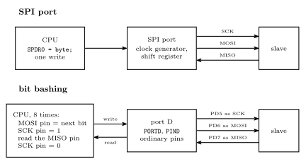
Figure 4: Who does the work. Above, with an SPI port: the program writes one byte to the data register and the port’s own clock generator and shift register produce all eight clock pulses and move all sixteen bits, while the CPU is free. Below, bit bashing the same transfer on three ordinary pins of port D: the CPU runs a loop that puts each bit on the MOSI pin, raises and lowers the SCK pin and reads the MISO pin, eight times over, through the port’s PORTD and PIND registers. The slave cannot tell the difference. The CPU is busy for the whole transfer, and the clock can go no faster than the loop.
Worked: an SPI master in software
Three spare pins of port D, plus one for the select, can be an SPI master in mode 0, most significant bit first, with nothing but the set, clear and test idioms of bit-masking:
#define BB_SS    4                 /* port D pins used for the software SPI */
#define BB_SCK   5
#define BB_MOSI  6
#define BB_MISO  7

void bb_init(void) {
    DDRD  |= (1<<BB_SS) | (1<<BB_SCK) | (1<<BB_MOSI);   /* outputs; MISO stays an input */
    PORTD |= (1<<BB_SS);                                /* nothing selected             */
    PORTD &= ~(1<<BB_SCK);                              /* the clock rests low          */
}

uint8_t bb_exchange(uint8_t out) {
    uint8_t in = 0;
    uint8_t i;

    for (i = 0; i < 8; i++) {
        if (out & 0x80) {                    /* put the top bit on MOSI           */
            PORTD |= (1<<BB_MOSI);
        } else {
            PORTD &= ~(1<<BB_MOSI);
        }
        out <<= 1;
        PORTD |= (1<<BB_SCK);                /* rising edge: both ends read       */
        in = (in << 1) | ((PIND >> BB_MISO) & 1);
        PORTD &= ~(1<<BB_SCK);               /* falling edge: the slave moves on  */
    }
    return in;
}
Used like the hardware version: pull BB_SS low, call bb_exchange once per byte, raise BB_SS. Reading MISO straight after raising SCK is safe, because the slave put that bit out on the previous falling edge, or when it was selected, and it stays put until the next falling edge.
What it costs.
- The CPU does everything. Each bit is several instructions, so the clock runs far slower than the 4 MHz the SPI port can make, and the program does nothing else meanwhile.
- Synchronous standards bash easily. The master makes the clock, so if the loop is held up between two edges, by an interrupt for instance, the transfer simply pauses. The slave waits for the next edge however long it takes.
- Asynchronous standards are harder. A bit-bashed UART has no clock to wait for, so every bit time has to be produced exactly, and an interrupt landing in the middle of a frame can wreck it.
Common mistakes
- Tx to Tx. The link is crossed: one end’s transmit pin goes to the other’s receive pin.
- Treating baud rate as bit rate. 9600 baud in 8N1 moves 7680 data bits a second, not 9600.
- Reading the bits most significant first. A UART sends bit 0 first.
- Leaving the parity bit out of the count. The rule is about the data bits and the parity bit together.
- Expecting parity to fix or locate an error, or to catch every error.
- Drawing the idle line at 0. Idle is 1, the start bit is 0, the stop bit is 1.
- Forgetting ground between two boards.
- Crossing SPI’s data wires. MOSI goes to MOSI and MISO to MISO: the names already say which end drives.
- Leaving out the pull-ups on an I²C bus. Nothing ever drives the lines high, so without them they never return to 1.
- Thinking memory could start a transfer. Memory is always a slave.
See also
- avr-usart — the ATmega324A’s USART: registers, baud-rate values, code and interrupts
- avr-spi — the ATmega324A’s SPI port: the exchange, timing, several slaves, registers, clock rate, code
- bit-masking — the set, clear and test idioms the bit-bashing code is made of
- shift-registers — parallel in, serial out, and the reverse
- logic-gates — XOR, which computes a parity bit
- timing-diagrams — how the waveforms here are drawn and read
- magnetic-disks — a disk sector, framed like a UART frame: preamble, data, ECC, gap
- io-board — the USB-serial device that joins the breadboard to a PC
- 2026-09-24-serial-io — Lecture 18 · 2026-10-05-more-io — Lecture 19