DBMS Fundamentals
What a database is, what a Database Management System is layered into, and what it is (and isn’t) responsible for. Introduced in 2026-02-23-conceptual-database-design-and-the-er-model and drilled in week2-tutorial-applied-class-1-intro-to-dbms-and-basic-erd.
Data, information, and where a database sits
Four definitions the course builds on top of each other:
| Term | Definition |
|---|---|
| Data | Facts and statistics collected together for reference or analysis, typically digitised |
| Information | Data put into meaningful and useful context and communicated to recipients who use it to make decisions |
| System | A set of components that interact to accomplish some purpose |
| Information system | A system that manages information |
An information system is built from five blocks — inputs, processes, outputs, databases and technology. This course is about the database block, which is where the data actually lives.
A database is a collection of related data or known facts that:
- represents some aspect of the real world — the mini-world, or Universe of Discourse (UoD);
- is a logically coherent collection of data with some inherent meaning;
- is designed, built and populated with data for a specific purpose, for an intended group of users and some preconceived applications;
- can be of any size and complexity;
- may be maintained manually or computerised.
The third point is the one that does the work later: a database is designed for a purpose, which is why design begins by fixing the UoD rather than by listing tables. See conceptual-database-design.
Data management — capturing, storing, retrieving, analysing, presenting and interpreting (large amounts of) data — is the skill the whole course is in service of. Three application sectors depend on it:
| Sector | Examples |
|---|---|
| Commerce | Cash management, pricing, employee records, purchasing, reordering, trend analysis |
| Government | Law enforcement, election commission, taxation, legal systems, transport and utilities, city councils |
| Science and engineering | Health and medicine, space exploration, geography (GIS), architecture, military and defence, telecommunications |
Banking is an example of an application area where data plays a central role.
What a DBMS is
A database management system (DBMS) is a software system that facilitates the processes of defining, constructing, manipulating and sharing databases among various users and applications. Those four verbs are the standard summary answer to “what is a DBMS”:
| Process | What it covers |
|---|---|
| Defining | Specifying the types, structures and constraints for the data — sql-ddl |
| Constructing | Storing the data on some storage medium controlled by the DBMS |
| Manipulating | Querying to retrieve specific data, updating to reflect changes in the mini-world, and generating reports — sql-select-statement, sql-dml |
| Sharing | Allowing multiple users and programs to access the database simultaneously |
The four components of a database system
The DBMS is only one piece. A database system has four:
| Component | What it is |
|---|---|
| The stored database | The collection of related information itself |
| The DBMS | The software that defines, constructs and manipulates the database |
| The applications | The programs, in specific languages, that manipulate the database |
| The users | People who use the system, either through the DBMS interface or through application programs |
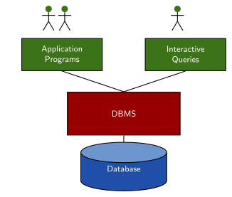
Figure 1: The database system. Users reach the stored database only through one of two front doors — an application program or an interactive query — and both go through the DBMS. Nothing touches the stored database directly.
Users are further split into database administrators, database designers, end users and application programmers. They reach the database through different interfaces by design: query languages for casual end users, programming-language interfaces for application programmers, and forms and commands for parametric users. GUIs, web-enabled interfaces, natural-language interfaces and speech I/O all sit on top of those. A parametric user is someone who runs the same canned transaction over and over.
Getting from the world to a stored database
Conceptual database design is two steps. Keep them separate before any diagram gets drawn:
- Identify the Universe of Discourse. The database will not model everything in the world, only some mini-world — see conceptual-database-design.
- Convert the UoD to a data model that a database can capture.
One example previews the whole arc of the course. An ER diagram has EMPLOYEE (attributes ID, Name, Salary) joined N:1 to DEPARTMENT (attributes Number, Name) through a WORKS FOR relationship. It maps to this relation:
Employee
| ID | Name | Salary | Department |
|---|---|---|---|
| 175 | Paris Lane | 60,000 | 2 |
| 467 | Anna Lee | 70,000 | 1 |
| 1023 | Ben Cho | 70,000 | 4 |
That one mapping is Modules 1 and 2 of this course: the conceptual model on top (entity-types-and-attributes, relationship-types) and the relational model beneath it (relational-model), joined by the mapping rules in er-to-relational-mapping. The WORKS FOR relationship has become the Department column of Employee, not a table of its own. Recognising that column as a foreign key is Module 2’s job (foreign-keys), and the reason a 1:N relationship collapses into a column is in er-to-relational-mapping.
Redundancy: the problem a designed database solves
Redundancy occurs when one fact is stored in more than one place. Take employee records split across two relations:
| ID | Name | Level |
|---|---|---|
| 1 | Paris | Developer |
| 2 | Anna | Manager |
| 3 | Ben | Manager |
| ID | Name | Salary |
|---|---|---|
| 1 | Paris | 60,000 |
| 2 | Anna | 70,000 |
| 3 | Ben | 70,000 |
Two separate facts are stored redundantly here. The ID/name pair is stored twice, once per relation. And assuming an employee’s salary corresponds directly to the level they hold, the fact “Manager earns 70,000” is stored once per manager rather than once — which is why Anna and Ben both carry 70,000 in their own row. Three costs follow:
- duplication of effort,
- wastage of storage space, and
- inconsistent data — the copies drift apart.
The design goal is therefore to minimise redundancy, not merely to store everything somewhere. The systematic machinery for doing that is functional-dependencies and normal-forms; the concrete failure modes are catalogued in update-anomalies. The other thing a database buys you over a pile of files is the ability to represent complex relationships among the data, which is what er-to-relational-mapping turns an ER diagram into.
Typical functions of a DBMS
| Function | What it means | Where it lands in this course |
|---|---|---|
| Data integrity maintenance | Defining and enforcing integrity constraints — restrictions placed on the data, based on the semantics (meaning) of the data | integrity-constraints |
| Query processing | A language simple enough to run a query and get data back in seconds, yet powerful enough to manage millions of tuples without crashing | sql-select-statement |
| Security management | Measures for securing the database against a variety of threats | database-access-control, sql-injection |
| Concurrency control | Control protocols for concurrent access to data files that guarantee serialisability | Deferred to later INFS courses |
| Backup and recovery | Recovering from hardware and software failures via the backup and recovery sub-system | Deferred to later INFS courses |
Integrity constraints are semantic — they come from what the data means, not from how it is stored. Examples: every employee must have a unique code; employee codes must be 4-digit integers; an employee must work in an existing department; an employee cannot work in multiple departments; an employee’s salary should not exceed their supervisor’s salary. Each of those is a constraint the DBMS can be told to police.
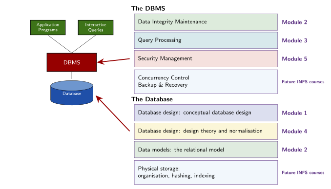
Figure 2: What the two boxes in Figure 1 decompose into, and which module of the course covers each piece: the functions of the DBMS, and what goes into designing and modelling the stored database. Everything greyed as future INFS courses is deferred to those courses.
The recovery example is the one worth remembering. A program transferring $200 from account A to account B is interrupted by a system failure partway through, so the deposit is never recorded in B. The DBMS restores the database to the state prior to the update and restarts the update program, rather than leaving the money in neither account. Concurrency control solves the neighbouring problem: thousands of people editing the same file while each assumes they are the only person using it. Serialisability is the guarantee the control protocols provide: whatever interleaving actually occurred, the result matches some order of running those accesses one at a time.
What a DBMS does — and doesn’t
The dividing line is a single rule: a DBMS enforces the design it is handed, it does not choose the design.
Enforcing integrity constraints, providing secure access, handling concurrent access, and backing up and recovering the database are all DBMS functions. Designing a database is not — and neither is normalising the relational schema (normal-forms) or recommending changes to the database design. Those are design-time decisions made by a human database designer, and no amount of running the database will make them happen by itself. In a list of candidate “DBMS functions”, the design-flavoured option is the odd one out every time.
The three-schema architecture
A DBMS describes the same data at three separate levels, so that each one can change without disturbing the others:
| Level | Describes |
|---|---|
| External level | Provides access to particular parts of the database to particular users, as one or more external views |
| Conceptual level | Describes the structure of the whole database for a community of users, as the conceptual schema |
| Internal level | Describes the physical storage structure of the database, as the internal schema |
The levels are joined by two named mappings: the external/conceptual mapping from each external view down to the conceptual schema, and the conceptual/internal mapping from the conceptual schema down to the internal schema and the stored database beneath it. The mappings are what make data independence possible — a change at one level is absorbed by re-writing the mapping rather than by rewriting the level above.
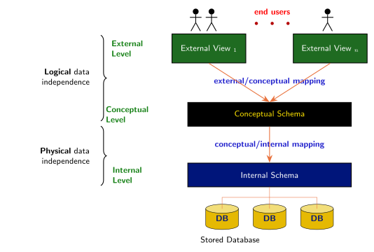
Figure 3: The three-schema architecture, with the two data-independence properties bracketed onto the level pairs they insulate. The colours — green external views, black/yellow conceptual schema, navy internal schema, gold cylinders — are the textbook’s, not INFS1200 notation; the course’s own ER house style is purple/magenta. Each independence property spans exactly one mapping: logical data independence rides the external/conceptual mapping, physical data independence rides the conceptual/internal one.
The external level is per-audience: a user or application sees the slice of the database relevant to it, not the whole thing, and SQL’s views (see sql-views) are the concrete mechanism for carving out that slice. The conceptual level is the one an ER diagram maps onto (see conceptual-database-design and relational-model), and the internal level — file organisation, hashing, indexing — is explicitly out of scope for this course.
Data independence
Data independence is the ability to change the schema at one level of a database system without having to change the schema at the next higher level. The three-schema architecture exists to deliver it in two flavours:
| Kind | What it buys you |
|---|---|
| Logical data independence | The ability to change the conceptual schema without changing the external views or the applications built on them |
| Physical data independence | The ability to modify the physical schema without changing the conceptual schema |
The course treats conceptual schema and logical schema as two names for the same middle level — physical data independence is stated interchangeably as “modify the physical schema without making changes to the logical schema”. So the two independence properties bracket that one level: logical data independence insulates the layer above it, physical data independence insulates it from the layer below.
Two claims that look right and aren’t: logical data independence is not about moving where data is physically stored (that is physical data independence), and the external level provides access to parts of the database, not the ability to change the schema of its relations. Both are distractors in multiple-choice questions. The correct statement is that physical data independence lets you modify the physical schema without changing the logical schema. The same matching is drilled in week2-tutorial-applied-class-1-intro-to-dbms-and-basic-erd.
Reading
Chapters 1 and 2 of Elmasri & Navathe, Fundamentals of Database Systems (the course textbook, available online via the UQ Library). The module that follows this one is Module 1, conceptual data modelling and ER diagrams — 2026-02-23-conceptual-database-design-and-the-er-model.