Conceptual Database Design
Conceptual design is everything that happens before a single table exists: deciding which slice of the world the database is about, and expressing that slice as an ER/EER diagram. It is a very important phase in designing a successful database application, and it follows a two-step procedure. Introduced in 2026-02-23-conceptual-database-design-and-the-er-model.
The Universe of Discourse
- Step 1 — identify the Universe of Discourse (UoD): the “mini-world” the database models. A database never models everything in the world, only the part an organisation actually needs to record.
- Step 2 — convert that UoD into a data model a database can capture.
Those two steps are the whole of conceptual design in this course: the world → the UoD → the data model. Everything in entity-types-and-attributes, relationship-types and specialisation-and-generalisation is machinery for step 2.
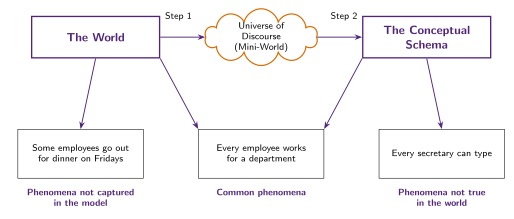
Figure 1: The two-step pipeline and the three categories of phenomena around the finished schema. The pipeline is the World → UoD → Data Model chain, and the three phenomenon boxes fan off the World and the Conceptual Schema. Only the middle box has an arrow from both, which is exactly what makes it common: true in the world and captured in the model.
The UoD is not a formality to get past. Every constraint drawn later — cardinality ratios, participation, disjointness — is read off the UoD rather than chosen arbitrarily (see relationship-constraints), so a vague or ambiguous UoD produces a diagram whose constraints can’t be justified. Where the UoD genuinely is ambiguous, that ambiguity becomes a design decision to record explicitly — see er-design-choices.
A model is never perfect
Around any conceptual schema there are three categories of phenomena (Figure 1):
| Category | Meaning | Example |
|---|---|---|
| Common phenomena | True in the world and captured in the model | “Every employee works for a department” |
| Phenomena not captured | True in the world, deliberately left out as irrelevant | “Some employees go out for dinner on Fridays” |
| Phenomena not true in the world | Captured by the model, but an over-general assumption | “Every secretary can type” |
The first category is the target. The second is fine and unavoidable — a model that captured everything would be the world itself. The third is the dangerous one: the schema will happily enforce a rule that reality violates, and the mismatch only surfaces once real data arrives.
What the ER model is for
The Entity-Relationship (ER) model provides a graphical representation of data entities, which is what makes it useful for defining a project’s scope and requirements with clients and businesses — it’s a communication artefact agreed on before implementation, not an implementation itself. Three questions run through the module: why conceptual modelling matters for designing a successful database application, how the ER model is used to do it, and how to evaluate the trade-offs between design choices by comparing alternative ER diagrams for the same system — the third of which is the whole content of er-design-choices.
An entity is a physical or conceptual object with data (attributes) associated with it. Crucially, the same real-world entity is recorded differently depending on the system’s requirements: an R&D organisation records an employee’s Degree and Field of Study, while a retail organisation records Sales Experience instead. There is no “correct” attribute list for a real-world thing in the abstract — only one that’s correct for a given UoD. See entity-types-and-attributes and relationship-types for the building blocks, specialisation-and-generalisation for the EER extension on top of them, and er-diagram-notation for the symbol legend. Reading a finished diagram back out is its own skill — interpreting-er-diagrams.
Where conceptual design sits
“Conceptual” is also the middle layer of a DBMS’s three-schema architecture (dbms-fundamentals) — the level that describes the whole database for a community of users, as opposed to any one user’s view of it. Conceptual design is where that schema gets written.
This course names no formal design lifecycle. The subject splits into three concerns, worked through in dependency order:
| Concern | Covered by |
|---|---|
| Database design — conceptual database design, then design theory and normalisation | This note, then functional-dependencies and normal-forms |
| Data models — the relational model, its integrity constraints, and ER-to-relational mapping | relational-model, integrity-constraints, er-to-relational-mapping |
| Physical storage — file organisation, hashing, indexing | Explicitly deferred to later INFS courses |
So the working pipeline is: conceptual design produces the ER/EER diagram; mapping turns it into a relational schema; SQL (sql-ddl) declares that schema; and normalisation refines it afterwards. Physical storage — the internal level of the three-schema architecture — never enters the picture here, which is exactly what physical data independence is supposed to buy.
That ordering is why conceptual mistakes are expensive. A decision that looks cosmetic on the diagram propagates into the schema and into the constraints the DBMS can actually enforce — the mapping errors dissected in week4-tutorial-case-study-3-dirt-road-driving are all downstream consequences of getting an entity’s identity or a relationship’s endpoint wrong at the conceptual stage.