Sample Mid-semester Exam #3
exercises
exam
past-paper
computer-systems
This is the third of UQ’s published sample mid-semester papers for CSSE2010/CSSE7201 Introduction to Computer Systems (see csse2010 for the course note). The cover sheet is dated Semester One Mid-semester Examinations, 2020, for St Lucia campus students. It allows 60 minutes of working time plus 10 minutes of reading time, and it is an open book examination — no electronic aids, but a Casio FX82-series or other UQ-approved calculator is permitted. There are 25 multiple-choice questions answered on a supplied answer sheet; a correct answer scores one mark, and an incorrect, missing or multiple answer scores zero. There is no penalty for guessing, so leaving a question blank is never the right move.
WarningAnswers are derived, not official
The source paper ships without an answer key, so every answer below was worked out during transcription rather than taken from UQ. Each one shows its reasoning so it can be checked rather than trusted; anything uncertain is flagged. Treat a disagreement between your working and the answer here as a reason to check both.
How to use this
Two ways. The first is a timed run: 25 questions in 60 minutes is a little over two minutes each, and on the website every answer is collapsed behind a disclosure triangle, so you can work the whole paper without seeing anything. The second is targeted practice — the index table below gives the week and the concept note for each question, so you can pick out just the questions covering one topic.
Note that the PDF build of this note has every answer expanded, because a PDF cannot hide them. Practise from the site version.
Question index
| Q | Topic | Week | Concept notes |
|---|---|---|---|
| 1 | Excess-256 representation | 1 | binary-number-representations |
| 2 | Hexadecimal, binary and octal | 1 | binary-number-representations |
| 3 | Signed magnitude range | 1 | binary-number-representations |
| 4 | Two’s to one’s complement | 1 | binary-number-representations |
| 5 | Reading a gate circuit | 1 | logic-gates |
| 6 | Boolean simplification | 2 | boolean-algebra |
| 7 | Building a sum of products | 2 | logic-gates · boolean-algebra |
| 8 | Expression from a truth table | 2 | boolean-algebra |
| 9 | NAND-only implementation | 2 | logic-gates · boolean-algebra |
| 10 | NAND latch behaviour | 3 | flip-flops-and-latches |
| 11 | Which circuit is a latch | 3 | flip-flops-and-latches |
| 12 | Timing diagram of a function | 2 | timing-diagrams · logic-gates |
| 13 | Multiplexer as a function | 2 | combinational-logic-blocks |
| 14 | Two’s complement addition | 2 | binary-number-representations |
| 15 | Detecting overflow | 2 | binary-number-representations |
| 16 | Interpreting an overflow | 2 | binary-number-representations |
| 17 | D flip-flop timing | 3 | flip-flops-and-latches · timing-diagrams |
| 18 | Load-or-swap register pair | 3 | sequential-circuits · shift-registers |
| 19 | Flip-flops for a sequence | 4 | counters · state-machines |
| 20 | Tracing a synchronous counter | 4 | counters |
| 21 | Counter width | 4 | counters |
| 22 | State diagram to state table | 4 | state-machines |
| 23 | Tracing a state machine | 4 | state-machines |
| 24 | ALU control settings | 5 | arithmetic-logic-unit |
| 25 | What the ALU cannot do | 5 | arithmetic-logic-unit |
Q1 — Excess-256 representation
What is \(-57_{10}\) expressed in 9-bit excess-256 format?
000111001
011000111
100111001
111000111
None of the above
TipAnswer
(b)
Excess-\(K\) stores a value \(v\) as the plain unsigned binary of \(v + K\). With \(K = 256\):
\[-57 + 256 = 199\]
and \(199 = 128 + 64 + 4 + 2 + 1 = 11000111_2\). Padded to nine bits that is \(011000111\).
The distractors are the recognisable wrong turns: (d) is the same magnitude bits with a leading 1 (as if the bias had been applied and then a sign bit added), and (a) and (c) are \(+57 = 00111001\) dressed up. See binary-number-representations.
Q2 — Hexadecimal, binary and octal
0xB9 is equal to
\(11001001_2\)
\(10101001_2\)
\(169_{10}\)
\(201_{10}\)
\(271_8\)
TipAnswer
(e)
Hex digits map straight onto nibbles: \(\mathrm{B} = 1011\) and \(9 = 1001\), so \(\mathrm{0xB9} = 10111001_2 = 185_{10}\).
None of (a)–(d) is 185: \(11001001_2 = 201\), \(10101001_2 = 169\), and (c) and (d) name those same two decimal values. So the paper has cross-paired its distractors — each wrong binary answer has its own decimal value sitting next to it as a separate option.
Octal groups the bits in threes from the right: \(10\,111\,001 \to 2, 7, 1\), so \(\mathrm{0xB9} = 271_8\). Checking, \(2 \times 64 + 7 \times 8 + 1 = 128 + 56 + 1 = 185\). See binary-number-representations.
Q3 — Signed magnitude range
A 6-bit binary number in signed magnitude representation can represent integers from
-32 to 32
-32 to 31
-31 to 31
0 to 31
None of the above
TipAnswer
(c)
Signed magnitude spends the most significant bit on the sign and leaves the remaining five bits as an ordinary unsigned magnitude, so the magnitude runs \(0\) to \(2^5 - 1 = 31\) and each magnitude gets both signs. The range is therefore \(-31\) to \(+31\).
Option (b) is the two’s complement range for six bits, which is the trap: two’s complement gets one extra negative value because it has no separate \(-0\). Signed magnitude wastes a code on \(100000 = -0\), which is why its range is symmetric and one value shorter. See binary-number-representations.
Q4 — Two’s to one’s complement
How can any n-bit binary number in two’s complement representation (other than \(-2^{n-1}\)) be converted to n-bit one’s complement representation?
By subtracting 1
By subtracting 1 and flipping all the bits
By subtracting the value of the most-significant bit
By adding the value of the most-significant bit
By flipping all the bits and subtracting the value of the most-significant bit
TipAnswer
(c)
Write the bit pattern as \(a_{n-1} a_{n-2} \dots a_0\). The two representations differ only in what the top bit is worth:
\[V_{2\text{'s}} = -a_{n-1}2^{n-1} + \sum_{i<n-1} a_i 2^i \qquad V_{1\text{'s}} = -a_{n-1}\left(2^{n-1}-1\right) + \sum_{i<n-1} a_i 2^i\]
So for a given bit pattern, \(V_{1\text{'s}} = V_{2\text{'s}} + a_{n-1}\). To keep the value the same while switching representation you therefore have to move the pattern down by \(a_{n-1}\) — that is, subtract the value of the most significant bit: 1 when the number is negative, 0 when it is positive.
Checking on 8 bits with \(-57\): two’s complement is \(11000111\), and subtracting 1 gives \(11000110\), which is indeed \(\overline{00111001}\), the one’s complement of \(-57\). And for \(+57 = 00111001\) the top bit is 0, so nothing is subtracted and the pattern is unchanged — which is right, because the two representations agree on positive numbers.
That last point is what rules out (a): “subtract 1” is correct for negatives but would corrupt every positive. The exclusion of \(-2^{n-1}\) in the question is because one’s complement cannot represent it at all. See binary-number-representations.
Q5 — Reading a gate circuit
What function does the following circuit implement?
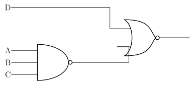
Figure 1: Question 5’s circuit: a three-input NAND on A, B and C, whose output is NORed with D.
\(A.B.C + \overline{D}\)
\(\overline{A.B.C} \oplus D\)
\(\overline{\overline{A.B.C} \oplus D}\)
\(\overline{\overline{A}.\overline{B}.\overline{C} + D}\)
\(\overline{\overline{A.B.C} + D}\)
TipAnswer
(e)
Read it inside out. The first gate is a three-input AND with a bubble, i.e. a NAND, so its output is \(\overline{A.B.C}\). That feeds one input of the second gate, which is an OR with a bubble — a NOR — with \(D\) on its other input. So the output is
\[\overline{\overline{A.B.C} + D}\]
which is exactly option (e), written with no simplification at all.
It is worth pushing it one step further to see what the circuit actually does, because that also disposes of (a) and (d). By De Morgan,
\[\overline{\overline{A.B.C} + D} = \overline{\overline{A.B.C}} \cdot \overline{D} = A.B.C.\overline{D}\]
so the circuit is “all three of A, B, C are 1 and D is 0”. Option (a) is \(A.B.C + \overline{D}\), an OR where the circuit has an AND, and option (d) simplifies to \((A+B+C).\overline{D}\), which is true whenever any of A, B, C is 1. Neither matches. See logic-gates.
Q6 — Boolean simplification
Which of the following logic functions is equivalent to \((A.\overline{B} + C).(\overline{\overline{A.C} + B})\) ?
\(A.\overline{B}\)
\(A.\overline{B}.C\)
\(A.\overline{B} + \overline{B}.C\)
\(A.\overline{B}.\overline{C} + \overline{A}.\overline{B}.C\)
None of the above
TipAnswer
(a)
Disputed by review. The question stem was mis-transcribed and has now been corrected: the source prints an inner bar over the whole product \(A.C\), so the second factor is \(\overline{\overline{A.C} + B}\), not \(\overline{\overline{A}.C + B}\). With the corrected stem I make the answer (b), not (a):
\[\overline{\overline{A.C} + B} = A.C.\overline{B} \qquad\text{so}\qquad \left(A.\overline{B} + C\right).A.C.\overline{B} = A.\overline{B}.C\]
since both products of the expansion collapse to \(A.\overline{B}.C\). The reasoning below is internally sound but solves the mis-transcribed expression, which is why it lands on (a). Work it yourself before trusting either, and check the bar placement in the PDF.
Deal with the complemented bracket first, using De Morgan twice:
\[\overline{\overline{A}.C + B} = \overline{\overline{A}.C} \cdot \overline{B} = \left(A + \overline{C}\right).\overline{B}\]
So the whole expression is
\[\left(A.\overline{B} + C\right)\left(A + \overline{C}\right)\overline{B}\]
Multiply out the first two brackets:
\[\left(A.\overline{B} + C\right)\left(A + \overline{C}\right) = A.\overline{B}.A + A.\overline{B}.\overline{C} + C.A + C.\overline{C}\]
\(C.\overline{C} = 0\) and \(A.A = A\), so this is \(A.\overline{B} + A.\overline{B}.\overline{C} + A.C\). The middle term is absorbed by the first (\(X + X.Y = X\)), leaving \(A.\overline{B} + A.C\).
Now bring back the trailing \(\overline{B}\):
\[\left(A.\overline{B} + A.C\right)\overline{B} = A.\overline{B} + A.\overline{B}.C = A.\overline{B}\]
again by absorption. See boolean-algebra.
Q7 — Building a sum of products
Which of the following circuits implements the function \(A.B + C.D\) ?
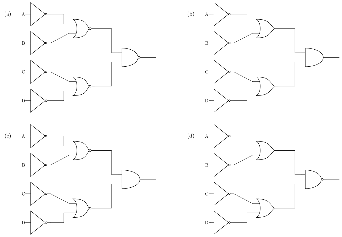
Figure 2: Question 7’s four candidate circuits, laid out as in the paper: (a) top left, (b) top right, (c) bottom left, (d) bottom right. All four invert every input first; they differ only in the pair of second-stage gates (NOR or OR) and in the output gate (NAND or AND).
- None of the above
TipAnswer
(d)
Every option starts by inverting all four inputs, so the second-stage gates always see \(\overline{A}, \overline{B}, \overline{C}, \overline{D}\). That makes the two useful De Morgan identities the whole question:
\[\overline{\overline{A} + \overline{B}} = A.B \qquad \overline{A} + \overline{B} = \overline{A.B}\]
The first says a NOR fed with inverted inputs is an AND; the second says a plain OR fed with inverted inputs is a NAND. Working the four options through:
| second stage | output gate | function | |
|---|---|---|---|
| (a) | NOR, so \(A.B\) and \(C.D\) | NAND | \(\overline{A.B \cdot C.D}\) |
| (b) | OR, so \(\overline{A.B}\) and \(\overline{C.D}\) | AND | \(\overline{A.B}\cdot\overline{C.D} = \overline{A.B + C.D}\) |
| (c) | NOR, so \(A.B\) and \(C.D\) | AND | \(A.B.C.D\) |
| (d) | OR, so \(\overline{A.B}\) and \(\overline{C.D}\) | NAND | \(\overline{\overline{A.B}\cdot\overline{C.D}} = A.B + C.D\) |
Only (d) gives the required \(A.B + C.D\), and it does it the standard way: a sum of products built entirely from inverting gates, with the final NAND undoing the double complement. Note that (b) is the exact complement of the answer — an easy option to pick if you forget the final bubble. See logic-gates and boolean-algebra.
Q8 — Expression from a truth table
Consider the logic function represented by the following truth table:
| A | B | C | X |
|---|---|---|---|
| 0 | 0 | 0 | 0 |
| 0 | 0 | 1 | 1 |
| 0 | 1 | 0 | 1 |
| 0 | 1 | 1 | 0 |
| 1 | 0 | 0 | 1 |
| 1 | 0 | 1 | 0 |
| 1 | 1 | 0 | 0 |
| 1 | 1 | 1 | 0 |
Which of the following expressions is equivalent to the function represented by this table?
\((A \oplus B).\overline{C} + (\overline{A + B}).C\)
\((A \oplus B) + C\)
\((A \oplus B) + \overline{A}.\overline{B}.C\)
\(\overline{A}.\overline{B}.C + \overline{A}.B.\overline{C} + A.B.\overline{C}\)
None of the above
TipAnswer
(a)
The function is 1 for exactly three input combinations — \(001\), \(010\) and \(100\) — so it is “exactly one of A, B, C is 1”. Its canonical sum of products is
\[X = \overline{A}.\overline{B}.C + \overline{A}.B.\overline{C} + A.\overline{B}.\overline{C}\]
Option (a) splits that on the value of C. When \(C = 0\) the second term vanishes and the first leaves \(A \oplus B\), which is 1 for exactly \(01\) and \(10\) — the minterms \(010\) and \(100\). When \(C = 1\) the first term vanishes and \(\overline{A + B}.C = \overline{A}.\overline{B}.C\) picks out \(001\) alone. Together that is exactly the three rows, so (a) matches.
Checking the others against the table is quick. (b) \((A \oplus B) + C\) is 1 at \(011\), where the table says 0. (c) is 1 at \(011\) for the same reason. (d) is the canonical form with its third term mistyped: it has \(A.B.\overline{C}\) (row \(110\), where the table says 0) instead of \(A.\overline{B}.\overline{C}\) (row \(100\), where the table says 1). See boolean-algebra.
Q9 — NAND-only implementation
Which of the following circuits is a NAND-gate only implementation of the following function:
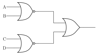
Figure 3: The function question 9 asks you to rebuild: NOR(A,B) ORed with NOR(C,D).
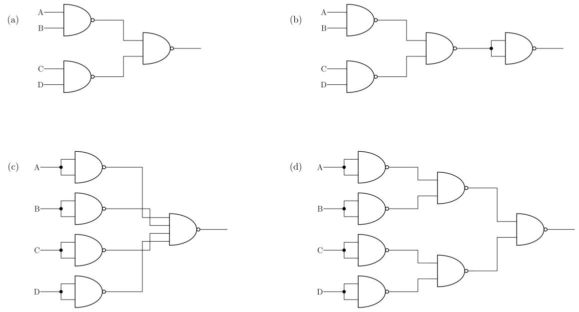
Figure 4: Question 9’s four candidate NAND-only circuits: (a) top left, (b) top right, (c) bottom left, (d) bottom right. A NAND with both inputs tied to the same signal — drawn here as a short fork with a junction dot — is a NAND used as an inverter.
- None of the above
TipAnswer
(d)
First write down what the target circuit computes. The two first-stage gates are NORs and the output gate is a plain OR, so
\[F = \overline{A+B} + \overline{C+D} = \overline{A}.\overline{B} + \overline{C}.\overline{D}\]
Now convert. A sum becomes a NAND of the two complemented terms, \(P + Q = \overline{\overline{P}\cdot\overline{Q}}\), so with \(P = \overline{A}.\overline{B}\) and \(Q = \overline{C}.\overline{D}\) the output gate must be a NAND fed with \(\overline{P}\) and \(\overline{Q}\). And \(\overline{P} = \overline{\overline{A}.\overline{B}}\) is itself just a NAND on \(\overline{A}\) and \(\overline{B}\). So:
\[F = \mathrm{NAND}\big(\mathrm{NAND}(\overline{A},\overline{B}),\ \mathrm{NAND}(\overline{C},\overline{D})\big)\]
The four inverters are NANDs with their inputs tied together, giving seven NAND gates in total — which is exactly circuit (d).
The others are all recognisable near-misses:
- (a) is \(\overline{\overline{A.B}\cdot\overline{C.D}} = A.B + C.D\) — the inputs are not inverted, so it computes the sum of the un-complemented products.
- (b) is (a) with an inverter, i.e. \(\overline{A.B + C.D}\). Try \(A=1, B=0, C=1, D=0\): the target gives \(0\), (b) gives \(1\).
- (c) inverts all four inputs correctly but then feeds them into a single four-input NAND, giving \(\overline{\overline{A}.\overline{B}.\overline{C}.\overline{D}}\) — an AND of all four where the target wants an OR of two pairs.
See logic-gates and boolean-algebra.
Q10 — NAND latch behaviour
Which truth table correctly captures the behaviour of the following latch circuit?
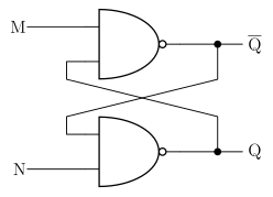
Figure 5: Question 10’s latch: two cross-coupled NAND gates, with M into the top gate (whose output is labelled Q-bar) and N into the bottom gate (whose output is labelled Q).
| M | N | Q | \(\overline{\mathrm{Q}}\) |
|---|---|---|---|
| 0 | 0 | Q | \(\overline{\mathrm{Q}}\) |
| 0 | 1 | 1 | 0 |
| 1 | 0 | 0 | 1 |
| 1 | 1 | 0 | 0 |
| M | N | Q | \(\overline{\mathrm{Q}}\) |
|---|---|---|---|
| 0 | 0 | 1 | 1 |
| 0 | 1 | 0 | 1 |
| 1 | 0 | 1 | 0 |
| 1 | 1 | Q | \(\overline{\mathrm{Q}}\) |
| M | N | Q | \(\overline{\mathrm{Q}}\) |
|---|---|---|---|
| 0 | 0 | 1 | 1 |
| 0 | 1 | 1 | 0 |
| 1 | 0 | 0 | 1 |
| 1 | 1 | Q | \(\overline{\mathrm{Q}}\) |
| M | N | Q | \(\overline{\mathrm{Q}}\) |
|---|---|---|---|
| 0 | 0 | 0 | 0 |
| 0 | 1 | 1 | 0 |
| 1 | 0 | 0 | 1 |
| 1 | 1 | Q | \(\overline{\mathrm{Q}}\) |
- None of the above
TipAnswer
(b)
This is the standard cross-coupled NAND latch, so both inputs are active low. Call the top gate’s output \(P\) (the one the paper labels \(\overline{\mathrm{Q}}\)) and the bottom gate’s output \(Q\). Then
\[P = \overline{M \cdot Q} \qquad Q = \overline{P \cdot N}\]
Work the four input combinations:
- M = 0, N = 0. A 0 on a NAND input forces its output to 1, so both gates output 1: \(Q = 1\) and \(\overline{\mathrm{Q}} = 1\). This is the forbidden combination — the two outputs are not complements.
- M = 0, N = 1. The top gate is forced, \(P = 1\). Then \(Q = \overline{1 \cdot 1} = 0\). So \(Q = 0\), \(\overline{\mathrm{Q}} = 1\) — a clear.
- M = 1, N = 0. The bottom gate is forced, \(Q = 1\). Then \(P = \overline{1 \cdot 1} = 0\). So \(Q = 1\), \(\overline{\mathrm{Q}} = 0\) — a set.
- M = 1, N = 1. Neither gate is forced, so \(P = \overline{Q}\) and \(Q = \overline{P}\), which is satisfied by either stored value. This is the hold state.
That is exactly table (b): \(1,1\) then \(0,1\) then \(1,0\) then hold.
The traps are worth naming. Table (a) puts the hold row at \(00\) and the forbidden row at \(11\) — that is the cross-coupled NOR latch, which has active-high inputs. Tables (c) and (d) get the hold row right but flip the set and clear rows, or write the forbidden state as \(0,0\) instead of \(1,1\) (NANDs cannot both output 0). See flip-flops-and-latches.
Q11 — Which circuit is a latch
Which of the following circuits is capable of acting as a latch? i.e. it has combinations of inputs (M,N) which allow a bit (0 or 1) to be stored, the latch to be set (Q=1) with a single input transition, and the latch to be cleared (Q=0) with a single input transition?
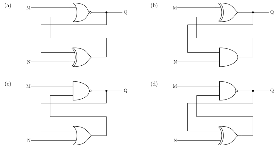
Figure 6: Question 11’s four candidate circuits, wired identically and differing only in the two gate types: (a) NOR over XOR, (b) XOR over AND, (c) NAND over OR, (d) NAND over XOR. In each, M feeds the top gate whose output is Q, N feeds the bottom gate, and the two are cross-coupled.
- None of the above
TipAnswer
(e)
All four circuits are wired the same way. Writing \(P\) for the bottom gate’s output, each is \(Q = g_{\text{top}}(M, P)\) and \(P = g_{\text{bot}}(Q, N)\), so the whole question is which pair of gate types gives a working memory element. For each circuit, substitute both equations into each other for all four \((M,N)\) and see whether the result is consistent (a stable state), forced (set or clear), or self-contradictory (the circuit oscillates).
(a) NOR over XOR — \(Q = \overline{M + P}\), \(P = Q \oplus N\).
| M N | working | result |
|---|---|---|
| 0 0 | \(P = Q\), so \(Q = \overline{Q}\) | oscillates |
| 0 1 | \(P = \overline{Q}\), so \(Q = Q\) | hold |
| 1 0 | \(Q = 0\), \(P = 0\) | clear |
| 1 1 | \(Q = 0\), \(P = 1\) | clear |
From the hold state \(01\), changing M gives \(11\) (a clear) but changing N gives \(00\) (oscillation). It can be cleared but never set.
(b) XOR over AND — \(Q = M \oplus P\), \(P = Q.N\). States: \(00\) clear, \(01\) hold, \(10\) set, \(11\) oscillates. The hold state \(01\) can reach the clear at \(00\) in one transition, but reaching the set at \(10\) needs two. Fails.
(c) NAND over OR — \(Q = \overline{M.P}\), \(P = Q + N\). With \(M = 0\) the NAND is forced, so \(Q = 1\) regardless of N; with \(M = 1, N = 1\) we get \(Q = 0\); with \(M = 1, N = 0\) it oscillates. There is no hold state at all, so this circuit has no memory.
(d) NAND over XOR — \(Q = \overline{M.P}\), \(P = Q \oplus N\). States: \(00\) and \(01\) both set (\(Q = 1\)), \(10\) oscillates, \(11\) holds. From the hold state \(11\), changing M gives a set, but changing N gives oscillation. It can be set but never cleared.
So none of the four does all three jobs, and the answer is (e). This is the point of the question: the classic latches are cross-coupled NOR pairs (hold at \(00\), set and clear on either input alone) or cross-coupled NAND pairs (hold at \(11\), as in Q10), and none of these four mixed pairs reproduces that. See flip-flops-and-latches.
Check this one. All eight gate symbols have now been read twice, independently, at high magnification against the source PDF, and both readings agree with the identifications above. The whole answer still turns on them, though: read the bottom gate of (a) as a NOR rather than an XOR and (a) becomes the textbook NOR latch, making it the answer instead.
Q12 — Timing diagram of a function
Which of the following timing diagrams represents the function \(A.B.C + \overline{B}.C\) ?
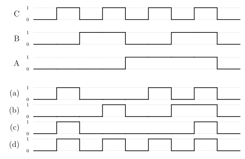
Figure 7: Question 12’s timing diagrams. The top three traces are the inputs C, B and A, which between them count 000 to 111 over the first eight slots and return to 000 in the ninth; the bottom four are the candidate outputs.
- None of the above
TipAnswer
(a)
The three input traces are a binary counter: C toggles every slot, B every two, A every four, so over the nine slots \(A B C\) runs \(000, 001, 010, 011, 100, 101, 110, 111\) and then back to \(000\). That turns the timing diagram into a truth table read left to right.
Evaluating \(F = A.B.C + \overline{B}.C\) slot by slot:
| slot | A B C | \(A.B.C\) | \(\overline{B}.C\) | F |
|---|---|---|---|---|
| 1 | 000 | 0 | 0 | 0 |
| 2 | 001 | 0 | 1 | 1 |
| 3 | 010 | 0 | 0 | 0 |
| 4 | 011 | 0 | 0 | 0 |
| 5 | 100 | 0 | 0 | 0 |
| 6 | 101 | 0 | 1 | 1 |
| 7 | 110 | 0 | 0 | 0 |
| 8 | 111 | 1 | 0 | 1 |
| 9 | 000 | 0 | 0 | 0 |
So the output is high in slots 2, 6 and 8 and low everywhere else, which is trace (a).
The other traces are each a different function of the same inputs: (d) is simply C, which would be the answer if the \(B\) terms were missing; (c) is high only in slots 2 and 8, i.e. it drops the \(101\) case; and (b) is high in slots 4, 7 and 8, which is a different function entirely. See timing-diagrams and logic-gates.
Q13 — Multiplexer as a function
Consider the following multiplexer. What must the inputs A,B,C,D be so that the multiplexer implements the function \(X = S_1 + S_0.G\)?
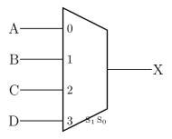
Figure 8: Question 13’s four-to-one multiplexer: inputs A, B, C and D on lines 0 to 3, selected by S1 S0, with output X.
A=0 B=G C=1 D=1
A=1 B=1 C=0 D=G
A=1 B=1 C=G D=0
A=G B=G C=1 D=1
A=G B=0 C=1 D=1
TipAnswer
(a)
A multiplexer whose select lines are the function’s own variables is just a lookup table: input \(n\) is passed through when \(S_1 S_0\) is the binary encoding of \(n\), so input \(n\) must carry whatever the function evaluates to for that combination of selects. Any variable not used as a select — here \(G\) — is allowed to appear on the data inputs.
Evaluating \(X = S_1 + S_0.G\) for each select value:
| \(S_1 S_0\) | line | \(X = S_1 + S_0.G\) | required input |
|---|---|---|---|
| 00 | 0 | \(0 + 0 \cdot G = 0\) | A = 0 |
| 01 | 1 | \(0 + 1 \cdot G = G\) | B = \(G\) |
| 10 | 2 | \(1 + 0 \cdot G = 1\) | C = 1 |
| 11 | 3 | \(1 + 1 \cdot G = 1\) | D = 1 |
So A=0, B=\(G\), C=1, D=1, which is option (a). Note how \(S_1 = 1\) makes the function true whatever \(S_0\) and \(G\) are, which is why both of the bottom two lines are hard-wired to 1. See combinational-logic-blocks.
Q14 — Two’s complement addition
What is the result of adding the 6-bit two’s complement numbers 010110 and 110011?
000001
001001
100101
101001
110111
TipAnswer
(b)
Add the bit patterns as if they were unsigned, then throw away anything past the sixth bit — that is the whole trick of two’s complement, and it is why the same adder works for signed and unsigned:
\[\begin{array}{r} 010110 \\ +\;110011 \\ \hline 1\,001001 \end{array}\]
Column by column from the right: \(0+1 = 1\); \(1+1 = 0\) carry 1; \(1+0+1 = 0\) carry 1; \(0+0+1 = 1\); \(1+1 = 0\) carry 1; \(0+1+1 = 0\) carry 1. Discarding the carry out of the top bit leaves \(001001\).
Sanity check in decimal: \(010110 = 22\), and \(110011\) is negative, with magnitude \(\overline{110011} + 1 = 001100 + 1 = 001101 = 13\), so it is \(-13\). And \(22 - 13 = 9 = 001001\). The result is positive and within range, so the discarded carry is not an overflow. See binary-number-representations.
Q15 — Detecting overflow
Which of the following operations will result in an overflow in 4-bit two’s complement arithmetic?
0100+0101
0100–0101
1001–0001
1001+0001
None of the above
TipAnswer
(a)
Four-bit two’s complement covers \(-8\) to \(+7\). Overflow means the true mathematical result falls outside that range; equivalently, it happens only when the two operands have the same sign and the result has the opposite sign.
| decimal | result | in range? | |
|---|---|---|---|
| (a) \(0100 + 0101\) | \(4 + 5\) | \(9\) | no — overflow |
| (b) \(0100 - 0101\) | \(4 - 5\) | \(-1\) | yes |
| (c) \(1001 - 0001\) | \(-7 - 1\) | \(-8\) | yes, just |
| (d) \(1001 + 0001\) | \(-7 + 1\) | \(-6\) | yes |
Only (a) escapes. Its bit sum is \(0100 + 0101 = 1001\), which reads as \(-7\) — two positives adding to a negative, the classic signature of overflow.
Option (c) is the near miss worth checking carefully: \(-8\) is representable in four bits (it is the one asymmetry of two’s complement), so \(1001 - 0001 = 1000 = -8\) is a legitimate result. Note also that (b) and (d) can never overflow at all, since adding numbers of opposite signs always produces a result no larger in magnitude than the larger operand. See binary-number-representations.
These same four operations also come up in Learning Lab 3 (Binary Arithmetic), in a different order and with the same answer, so this is a question the course drills rather than a one-off. See week2-lab-binary-arithmetic.
Q16 — Interpreting an overflow
Consider the binary addition operation 1001 + 1110. Which of the following statements is true if the numbers are interpreted as two’s complement?
The result is negative and no overflow occurs
The result should be negative but overflow occurs
The result is positive and no overflow occurs
The result should be positive but overflow occurs
The result is zero
TipAnswer
(b)
As two’s complement values, \(1001 = -7\) and \(1110 = -2\), so the true answer is \(-9\) — outside the \(-8\) to \(+7\) range, hence an overflow. The correct answer “should be negative”, which rules out (d).
Doing the addition confirms it:
\[\begin{array}{r} 1001 \\ +\;1110 \\ \hline 1\,0111 \end{array}\]
Discarding the carry leaves \(0111 = +7\): two negatives have produced a positive, which is precisely the overflow signature and is why (a) and (c) are wrong. The carry out of the top bit is not itself the overflow flag here — a two’s complement addition can produce a carry out with no overflow at all (as in Q14). See binary-number-representations.
Q17 — D flip-flop timing
Consider the flip-flop circuit shown below and the associated CLK and output (Q) signals. Which timing diagram shows input (A) values over time which would have resulted in the given output (Q).
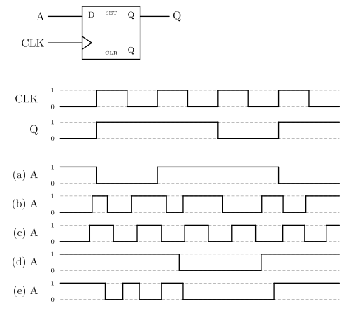
Figure 9: Question 17’s positive-edge-triggered D flip-flop, the given CLK and Q traces, and the five candidate A inputs.
TipAnswer
(d)
The clock triangle on the symbol has no bubble, so this is a positive-edge-triggered D flip-flop: at each rising clock edge, Q takes the value D had just before that edge, and between edges Q holds. There are four rising edges in the diagram. Reading the Q trace against them:
| edge | Q before | Q after | so A just before the edge must be |
|---|---|---|---|
| 1 | 0 | 1 | 1 |
| 2 | 1 | 1 | 1 |
| 3 | 1 | 0 | 0 |
| 4 | 0 | 1 | 1 |
So the requirement is \(A = 1, 1, 0, 1\) at the four edges. Checking each candidate:
- (a) goes low right at the first edge and only comes back high at the second, so it reads \(1, 0, \dots\) — wrong at edge 2. (Its transitions also land exactly on the clock edges, which would be a setup-time violation in real hardware.)
- (b) is high at edges 1, 2 and 3, so Q would stay high at edge 3 instead of falling.
- (c) gets edges 1, 2 and 3 right but is low at edge 4, so Q would not rise again.
- (d) is high until part-way through the third clock cycle and low until part-way through the fifth, giving \(1, 1, 0, 1\) — a match, and with every transition comfortably away from a clock edge.
- (e) has already gone low before edge 2, so Q would fall there.
Only (d) works. The useful habit here is to ignore the shape of A between edges entirely: a D flip-flop samples, so only the four instants matter. See flip-flops-and-latches and timing-diagrams.
Q18 — Load-or-swap register pair
Consider the following circuit. If \(A_1\) is 1 and \(A_0\) is 0, what will be the values of \(Q_1\) and \(Q_0\) after three rising clock edges if FN is 0 for one rising clock edge then 1 for two rising clock edges?
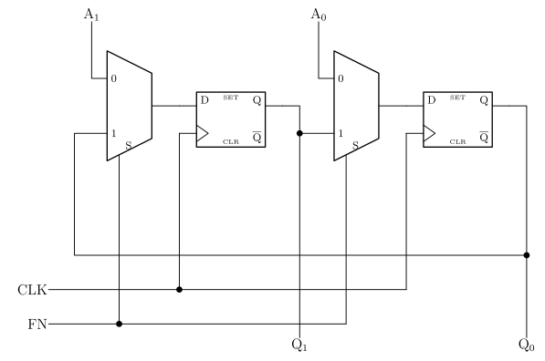
Figure 10: Question 18’s circuit: two D flip-flops, each fed by a multiplexer selected by FN. With FN=0 each flip-flop loads its own A input; with FN=1 each loads the other flip-flop’s output, so the pair swaps.
\(Q_1 = 0\) \(Q_0 = 0\)
\(Q_1 = 0\) \(Q_0 = 1\)
\(Q_1 = 1\) \(Q_0 = 0\)
\(Q_1 = 1\) \(Q_0 = 1\)
Insufficient information is provided to determine the values
TipAnswer
(c)
Read the two multiplexers first. Both take their select from FN, so FN picks one of two behaviours for the whole circuit:
- FN = 0 selects line 0 on each multiplexer, which is \(A_1\) for the left flip-flop and \(A_0\) for the right one. This is a parallel load.
- FN = 1 selects line 1. The left multiplexer’s line 1 comes from the long feedback rail running back from \(Q_0\), and the right multiplexer’s line 1 comes from \(Q_1\). So \(D_1 = Q_0\) and \(D_0 = Q_1\) — the two bits swap.
Both flip-flops share the clock, so the swap happens simultaneously and there is no race: each captures the other’s old value.
Now trace the three edges with \(A_1 A_0 = 10\):
| edge | FN | action | \(Q_1 Q_0\) after |
|---|---|---|---|
| 1 | 0 | load \(A_1 A_0\) | 1 0 |
| 2 | 1 | swap | 0 1 |
| 3 | 1 | swap | 1 0 |
After three edges \(Q_1 = 1\) and \(Q_0 = 0\), which is option (c). Two swaps cancel, so the pair is back to what the load put there — which is the real point of the question.
Option (e) is the trap for anyone who worries about the initial contents of the flip-flops, but the first edge loads both of them from \(A_1\) and \(A_0\), so whatever they held beforehand is irrelevant. See sequential-circuits and shift-registers.
Q19 — Flip-flops for a sequence
A sequential circuit has four outputs (\(X_3,X_2,X_1,X_0\)) which advance through the following repeating sequence:
\[X_3X_2X_1X_0: \quad 0000 \to 0001 \to 0011 \to 0111 \to 1111 \to 1100 \to 0000 \to \dots\]
What is the minimum number of flip-flops needed to implement this circuit?
2
3
4
6
8
TipAnswer
(b)
Count the distinct values in the cycle: \(0000\), \(0001\), \(0011\), \(0111\), \(1111\), \(1100\) — six of them, and then it repeats. The flip-flops have to hold the state, not the outputs, and \(n\) flip-flops give \(2^n\) states, so we need the smallest \(n\) with \(2^n \ge 6\):
\[2^2 = 4 < 6 \le 8 = 2^3\]
so three flip-flops, which is (b).
The obvious answer is (c), four — one flip-flop per output bit. That works, and it is what you would build if you wanted the outputs straight off the flip-flops with no extra logic. But the question asks for the minimum, and with only six states in the cycle you can encode the state in three bits and derive the four outputs combinationally from that encoding. The cost is a block of output logic; the saving is a flip-flop.
Note that two would not do: four states cannot distinguish six points in the cycle, and each state must have a unique successor, so distinct steps need distinct encodings. See counters and state-machines.
Q20 — Tracing a synchronous counter
What sequence will the following synchronous counter count through, if it starts at \(Q_1Q_0 = 00\)?
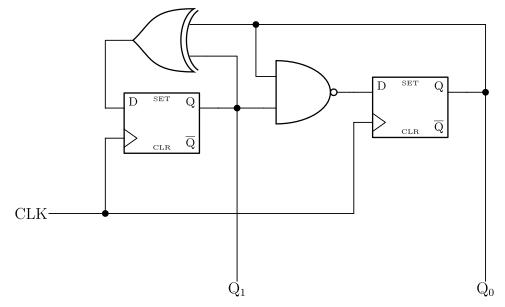
Figure 11: Question 20’s counter. The XOR is drawn mirrored, as in the paper: its output faces left into the first flip-flop’s D input and its two inputs face right onto the Q1 and Q0 lines. The NAND takes the same two signals and drives the second flip-flop.
\(Q_1Q_0\): \(00 \to 01 \to 10 \to 11 \to 00 \to \dots\)
\(Q_1Q_0\): \(00 \to 01 \to 11 \to 00 \to \dots\)
\(Q_1Q_0\): \(00 \to 01 \to 11 \to 10 \to 00 \to \dots\)
\(Q_1Q_0\): \(00 \to 10 \to 11 \to 00 \to \dots\)
\(Q_1Q_0\): \(00 \to 11 \to 00 \to \dots\)
TipAnswer
(b)
Both gates see the same two signals — the top rail carries \(Q_0\) back from the second flip-flop, and the vertical line carries \(Q_1\) from the first — so the excitation equations are
\[D_1 = Q_1 \oplus Q_0 \qquad D_0 = \overline{Q_1 \cdot Q_0}\]
Both flip-flops share the clock, so on each edge they update together from the current state. Building the state table:
| \(Q_1Q_0\) | \(D_1 = Q_1 \oplus Q_0\) | \(D_0 = \overline{Q_1.Q_0}\) | next |
|---|---|---|---|
| 00 | 0 | 1 | 01 |
| 01 | 1 | 1 | 11 |
| 11 | 0 | 0 | 00 |
| 10 | 1 | 1 | 11 |
Starting at \(00\) the counter goes \(00 \to 01 \to 11 \to 00\), a three-state cycle, which is option (b).
The fourth row is the unused state. It is worth checking because a counter that can lock up in an unused state is broken: \(10 \to 11\), which is inside the main cycle, so the circuit self-corrects within one clock. See counters.
Q21 — Counter width
What’s the minimum number of flip-flops needed to build a synchronous binary counter capable of counting from 0 to 16 (inclusive)?
3
4
5
16
17
TipAnswer
(c)
“0 to 16 inclusive” is seventeen values, not sixteen — that is the whole question. With \(n\) flip-flops a binary counter has \(2^n\) distinct states, so we need \(2^n \ge 17\):
\[2^4 = 16 < 17 \le 32 = 2^5\]
so five flip-flops. Four would get to 15 and no further.
Option (b) is what you get by reading “16” as the count of values rather than the last value, and options (d) and (e) confuse flip-flops with states — a one-hot ring counter would need one flip-flop per state, but a binary counter encodes the count in binary, which is exactly why it only needs \(\lceil \log_2 17 \rceil = 5\). See counters.
Q22 — State diagram to state table
Consider the state diagram below.
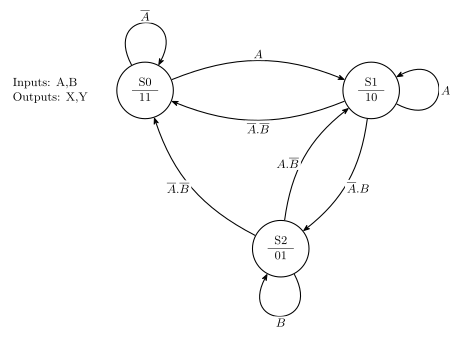
Figure 12: Question 22’s state diagram. Three states, each labelled with its name over its X,Y output pair; every arc carries the condition on the inputs A and B under which it is taken.
Which of the following is an equivalent state table?
| Current State | AB=00 | AB=01 | AB=10 | AB=11 | Outputs (X,Y) |
|---|---|---|---|---|---|
| S0 | S0 | S0 | S1 | S1 | 11 |
| S1 | S0 | S2 | S1 | S2 | 10 |
| S2 | S0 | S2 | S1 | S2 | 01 |
| Current State | AB=00 | AB=01 | AB=10 | AB=11 | Outputs (X,Y) |
|---|---|---|---|---|---|
| S0 | S0 | S1 | S0 | S1 | 11 |
| S1 | S0 | S2 | S1 | S1 | 10 |
| S2 | S0 | S1 | S2 | S2 | 01 |
| Current State | AB=00 | AB=01 | AB=10 | AB=11 | Outputs (X,Y) |
|---|---|---|---|---|---|
| S0 | S0 | S1 | S0 | S1 | 00 |
| S1 | S0 | S2 | S1 | S1 | 01 |
| S2 | S0 | S2 | S1 | S2 | 10 |
| Current State | AB=00 | AB=01 | AB=10 | AB=11 | Outputs (X,Y) |
|---|---|---|---|---|---|
| S0 | S0 | S0 | S1 | S1 | 11 |
| S1 | S0 | S2 | S1 | S1 | 10 |
| S2 | S0 | S2 | S1 | S2 | 01 |
- None of the above
TipAnswer
(d)
Take each state’s outgoing arcs and expand their conditions into the four values of \(AB\). Note that the diagram’s labels do not all name both inputs — \(A\) on its own covers \(AB = 10\) and \(AB = 11\), and \(B\) on its own covers \(01\) and \(11\) — which is where most of the difference between the options lives.
S0 has two arcs: a self-loop on \(\overline{A}\) and an arc to S1 on \(A\). So \(AB = 00, 01 \to\) S0 and \(AB = 10, 11 \to\) S1.
S1 has three arcs: a self-loop on \(A\), an arc to S0 on \(\overline{A}.\overline{B}\), and an arc to S2 on \(\overline{A}.B\). So \(AB = 00 \to\) S0, \(01 \to\) S2, and \(10, 11 \to\) S1 (both covered by the bare \(A\)).
S2 has three arcs: a self-loop on \(B\), an arc to S1 on \(A.\overline{B}\), and an arc to S0 on \(\overline{A}.\overline{B}\). So \(AB = 01, 11 \to\) S2 (both covered by the bare \(B\)), \(10 \to\) S1 and \(00 \to\) S0.
Each state’s arcs cover all four combinations exactly once, which is the completeness check worth doing before comparing anything. The outputs are read straight off the bottom half of each circle: S0 is 11, S1 is 10, S2 is 01.
That gives table (d). The near-miss is (a), which is identical except that it sends S1 to S2 on \(AB = 11\) — that would be right if S1’s self-loop were labelled \(A.\overline{B}\) rather than plain \(A\). Table (b) mangles S0’s row (sending it to S1 on \(01\) instead of \(10\)), and (c) has the outputs shifted onto the wrong states. See state-machines.
The table you have just built is the 2-dimensional state table of the lab’s design pipeline — one row per state, one next-state column per input combination. It is step 2 of six; Beyond the paper below walks the remaining four on a machine of the same size, ending in the waveforms that circuit produces.
Q23 — Tracing a state machine
Consider the state machine represented by the state diagram shown in question 22 (see Q22). What sequence of states is traversed if the machine starts in state S0 and A goes through the sequence 1010101 and B is always the inverse of A?
S0→S0→S1→S2→S1→S2→S1→S2
S0→S1→S1→S2→S1→S2→S1→S2
S0→S1→S2→S2→S1→S2→S1→S2
S0→S1→S2→S1→S2→S1→S2→S1
None of the above
TipAnswer
(d)
B is the inverse of A, so the input pairs alternate between \(AB = 10\) and \(AB = 01\): seven values of A give the sequence \(10, 01, 10, 01, 10, 01, 10\).
From the state table derived in Q22, only two columns are ever used:
- \(AB = 10\): S0 → S1, S1 → S1, S2 → S1
- \(AB = 01\): S0 → S0, S1 → S2, S2 → S2
Starting in S0:
| step | AB | from | to |
|---|---|---|---|
| 1 | 10 | S0 | S1 |
| 2 | 01 | S1 | S2 |
| 3 | 10 | S2 | S1 |
| 4 | 01 | S1 | S2 |
| 5 | 10 | S2 | S1 |
| 6 | 01 | S1 | S2 |
| 7 | 10 | S2 | S1 |
So the machine goes S0→S1→S2→S1→S2→S1→S2→S1, which is (d) — eight states listed, being the start state plus one per input.
The trap is (a), which begins S0→S0 as if the first input left the machine where it was; but the first input has \(A = 1\), and S0 only stays put on \(\overline{A}\). Options (b) and (c) each stutter once in the middle, which cannot happen because the input never repeats. See state-machines. For what a traced machine looks like once it is built out of flip-flops and gates, see Beyond the paper below.
Q24 — ALU control settings
Consider the ALU bit slice below (not the same as seen previously).
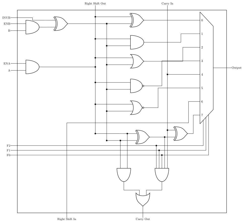
Figure 13: Question 24’s ALU bit slice. ENA/ENB/INVB condition A and B into the internal X and Y rails; five gates and the adder compute their functions in parallel, and the eight-way multiplexer picks one under F2 F1 F0. Right Shift Out is the X rail itself, so selecting input 6 (Right Shift In) hands each slice the bit from the slice to its left.
For an ALU made up of 8 of the bit slices above, which of the following control input settings will result in the ALU output being \(\overline{A}.B\) (bitwise)? (The “Right Shift In” control input refers to that for the most significant bit; the “Carry in” control input refers to that for the least significant bit.)
ENA=1 ENB=1 INVB=0 \(F_2\)=0 \(F_1\)=0 \(F_0\)=0 Right Shift In=1 Carry in=1
ENA=1 ENB=1 INVB=0 \(F_2\)=0 \(F_1\)=0 \(F_0\)=1 Right Shift In=1 Carry in=1
ENA=1 ENB=1 INVB=1 \(F_2\)=0 \(F_1\)=0 \(F_0\)=1 Right Shift In=1 Carry in=1
ENA=1 ENB=1 INVB=0 \(F_2\)=0 \(F_1\)=1 \(F_0\)=1 Right Shift In=1 Carry in=1
ENA=1 ENB=1 INVB=1 \(F_2\)=1 \(F_1\)=0 \(F_0\)=1 Right Shift In=1 Carry in=1
TipAnswer
(e)
Two things have to be read off the figure: what the conditioning gates do to A and B, and which function each value of \(F_2F_1F_0\) selects.
Conditioning. A goes through one AND gate with ENA and nothing else — note there is no INVA on this slice — so the internal signal is
\[X = A \cdot \text{ENA}\]
B goes through an AND with ENB and then an XOR with INVB, and XORing with 1 is inversion, so
\[Y = (B \cdot \text{ENB}) \oplus \text{INVB}\]
Every option sets ENA = ENB = 1, so \(X = A\) and \(Y = B \oplus \text{INVB}\); INVB is the only thing left that can change the data.
Function select. Following each mux input back to its source in the figure gives:
| \(F_2F_1F_0\) | input | function |
|---|---|---|
| 000 | 0 | \(X \oplus Y\) |
| 001 | 1 | \(X \cdot Y\) |
| 010 | 2 | \(X + Y\) |
| 011 | 3 | \(\overline{X \cdot Y}\) |
| 100 | 4 | Carry In |
| 101 | 5 | \(\overline{X + Y}\) |
| 110 | 6 | Right Shift In |
| 111 | 7 | \(X \oplus Y \oplus C_{in}\) (the sum) |
Now, how do you get \(\overline{A}.B\) from a slice that cannot invert A? Push the complement onto the other side with De Morgan:
\[\overline{A}.B = \overline{A + \overline{B}}\]
So take \(X = A\) and \(Y = \overline{B}\) (which needs INVB = 1) and select the NOR, which is \(F_2F_1F_0 = 101\). That is option (e).
Checking the others: (a) is INVB = 0 with the XOR, giving \(A \oplus B\); (b) is INVB = 0 with the AND, giving \(A.B\); (c) is INVB = 1 with the AND, giving \(A.\overline{B}\) — the mirror image of what was asked, and the most tempting wrong answer; (d) is INVB = 0 with the NAND (\(F_2F_1F_0 = 011\)), giving \(\overline{A.B}\), which is the complement of (b) rather than anything with a single complemented variable.
Right Shift In and Carry in are set to 1 in every option, so they cannot distinguish the answers — and neither reaches the output anyway once \(F_2F_1F_0\) selects a logic function. See arithmetic-logic-unit.
Q25 — What the ALU cannot do
For an ALU made up of 8 of the bit slices shown in question 24 above (see Q24), which of the following control input function settings can NOT be used to output \(\overline{B}\) (bitwise) — assuming other control inputs are chosen appropriately?
\(F_2\)=0 \(F_1\)=0 \(F_0\)=0 XOR
\(F_2\)=0 \(F_1\)=1 \(F_0\)=0 OR
\(F_2\)=0 \(F_1\)=1 \(F_0\)=1 NAND
\(F_2\)=1 \(F_1\)=0 \(F_0\)=1 NOR
None of the above
TipAnswer
(c)
The question hands you the function each select code picks, so the work is in what the conditioning gates can produce. From Q24, the two internal signals are \(X = A \cdot \text{ENA}\) and \(Y = (B \cdot \text{ENB}) \oplus \text{INVB}\), so the reachable values are:
| ENA | \(X\) | ENB | INVB | \(Y\) | |
|---|---|---|---|---|---|
| 0 | \(0\) | 0 | 0 | \(0\) | |
| 1 | \(A\) | 0 | 1 | \(1\) | |
| 1 | 0 | \(B\) | |||
| 1 | 1 | \(\overline{B}\) |
The critical asymmetry is that X can be forced to 0 but never to 1, because there is no INVA on this slice. Y, having the INVB stage, can be forced to either constant.
With that in hand:
- (a) XOR, \(X \oplus Y\). Set ENA = 0 so \(X = 0\), and ENB = INVB = 1 so \(Y = \overline{B}\). Then \(0 \oplus \overline{B} = \overline{B}\), so this one works.
- (b) OR, \(X + Y\). Same settings: \(0 + \overline{B} = \overline{B}\), so this one works too.
- (d) NOR, \(\overline{X + Y}\). Set \(X = 0\) and \(Y = B\) (ENB = 1, INVB = 0). Then \(\overline{0 + B} = \overline{B}\), which works.
- (c) NAND, \(\overline{X \cdot Y}\). To get \(\overline{B}\) out of a NAND you need \(X \cdot Y = B\), which requires \(X = 1\) with \(Y = B\) (or \(X = B\), which is not available either — A and B cannot be swapped). But \(X \in \{0, A\}\), so \(X\) can never be a constant 1. Every reachable combination fails: \(X = 0\) gives a constant 1; \(X = A\) gives \(\overline{A.B}\), \(\overline{A.\overline{B}}\), \(\overline{A}\) or 1, none of which is \(\overline{B}\). This is the one that cannot be done.
So (c) is the setting that cannot produce \(\overline{B}\). The general lesson is the one from arithmetic-logic-unit: forcing a data input to a constant is what lets one ALU compute unary functions, and here that trick works on the B side but only half-works on the A side.
Beyond the paper — from state diagram to wired circuit
Q22 asks for one step of a longer road — state diagram to state table — and Q23 asks you to walk the machine along it. Learning Lab 8 (State Machines) names the whole road and makes you travel all of it: “do hand design first — state diagram → state table → next state logic and output logic”, and then “enter the circuit into Logisim and simulate it”.
This follows the design task of Learning Lab 8 (State Machines). Its Design Task 1, a detector for the sequence
001, is worked through state diagram, state tables, encoding, Boolean expressions and logic diagram in week5-lab-state-machines. This section maps the lab’s design steps onto this paper’s questions and adds a timing diagram of the finished design, using the encoding and expressions from that note.
The pipeline, and where this paper cuts into it
| Step | What Lab 8 asks for | Tested here by |
|---|---|---|
| 1 | Draw the state diagram — one circle per state, name over output, an arrow per input condition | Q22 reads one; Q23 walks one |
| 2 | Write the 2-dimensional state table — one row per state, one next-state column per input combination | Q22, which is exactly this conversion |
| 3 | Choose a state encoding — the number of flip-flops and their values in each state. “Examine different options for state encoding!” | Q19, Q21 — both are the “how many flip-flops” half of this step |
| 4 | Write the 1-dimensional state table — one row per (state, input) combination, with the D inputs spelled out | not examined directly; it is the working for step 5 |
| 5 | Derive Boolean expressions for the outputs and the flip-flop D inputs, in terms of the Q outputs and the inputs | Q20 runs this backwards, reading a counter’s next-state logic off its circuit |
| 6 | Enter the circuit and simulate | the timing diagram below is what that simulation shows |
Step 3 is the one the lab shouts about, and it is worth seeing why. For the 001 detector, the obvious binary assignment \(S_0S_1S_2S_3 = 00,01,10,11\) leaves several product terms in each next-state expression and nothing collapses; the assignment week5-lab-state-machines settles on instead —
\[S_0 = 01 \qquad S_1 = 00 \qquad S_2 = 10 \qquad S_3 = 11\]
— makes one flip-flop input collapse to a bare wire. Nothing about the state diagram changed; only the numbers written on the states did.
What the machine does on a clock
\[D_0 = S \qquad D_1 = \overline{Q_0}\,(Q_1 + \overline{S}) = \overline{Q_0} \cdot \overline{\overline{Q_1}\,.\,S} \qquad X = Q_1 . Q_0\]
Three chips build that: a 74HCT74 for the two flip-flops, one NAND of a 74HCT00, and two ANDs of a 74HCT08 — which is the lab’s “are you a bad enough dude to implement a sequence detector with just three chips?” challenge, answered. The logic diagram is drawn in week5-lab-state-machines; what is worth adding here is the other view of the same machine, because it is the one Q23 and Q17 are really asking about — where each value sits in time.
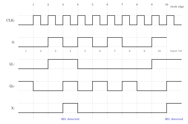
Figure 14: The 001 detector running on the first ten bits of the input sequence from Lab 8’s Design Task 1. Read it in columns: the dashed verticals are the ten rising clock edges, the number under the S track is which input bit is being presented, and each of Q1, Q0 and X holds the value it took at the previous edge. The offset is the whole point. Bit 3 completes the first 001 while it sits in the interval before edge 3, but X only goes high after edge 3 has been taken, so the pulse on X appears one column to the right of the bit that caused it - even though the lab’s S and X strings are written aligned by index. Q0 is a delayed copy of S, which is what D0 = S means in the time domain, and X is high exactly where Q1 and Q0 are both high. The two blue notes are added here, not on the slide.
Three things come off that picture, and each is an exam trap somewhere:
- The input is sampled, not watched. Nothing happens to \(Q_1\) or \(Q_0\) between edges, however \(S\) wriggles. This is the whole content of Q17, where the question is which candidate \(A\) waveform could have produced the given \(Q\) — and the answer only ever depends on what \(A\) was doing at the edges.
- A Moore output lags the input that caused it. Bit 3 completes the first
001, but the machine is only in \(S_3\) after edge 3 has happened, so \(X\) rises after that edge and stays up for one clock period. The lab’s two bit strings are aligned by index, not by time. - \(Q_0\) is \(S\) delayed by one clock, which is exactly what \(D_0 = S\) means once the flip-flop is in the path. Encoding choices that make a D input equal an existing signal turn a gate into a wire, and that is why step 3 of the pipeline is worth the effort.
Two more questions the same design answers
- “How many flip-flops does this machine need?” — Q19 and Q21. Count the states, then count the flip-flops: \(N\) flip-flops hold \(2^N\) distinct patterns, so \(N = \lceil \log_2(\text{number of states}) \rceil\). Four states here, hence the two tracks \(Q_1\) and \(Q_0\) in the waveform.
- “Moore or Mealy?” — \(X = Q_1 . Q_0\) mentions the state and nothing else, which is what makes this Moore. A Mealy output would have \(S\) in its expression too, and would then be free to change part-way through a clock period rather than only just after an edge — the flat-topped one-period-wide pulses on the \(X\) track are the visible signature of Moore. CSSE2010 sticks to Moore; see state-machines.
Your score
Reload the page to clear your answers.